


Theory of Operation
3-26
2715 Spectrum Analyzer Service Manual
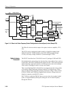
down the strobe driver amplifier in the 1st LO BUFFER module.
Also, U240 serves as a count selector switch. It selects either the LFVCO signal
or the 1st LO beat signal (from the PLCFC board) for counting by the micropro-
cessor. R241 is part of a TTL to ECL level shifter, the remainder of which is
located on the microprocessor board.
U510B provides a lock status indicator for the inner loop so that a lock failure
can interrupt the microprocessor through circuitry on the PLCFC board.
The HFVCO receives supplementary power supply regulation by means of
U122.
The LFVCO receives supplementary power supply regulation by means of U123,
Q223, and associated parts.
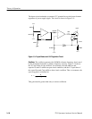
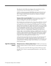
The output of the phase gate in the 1st LO Buffer module may either be a beat
note (when loop is unlocked) or a phase error voltage for maintenance of lock.
Thus, the output of the phase gate is split into two paths.
Beat signals in the range of approximately 3 kHz through 11 MHz are passed
through a chain including U614, a low pass filter, U723, and U720. They drive a
Schmitt trigger circuit (Q630 through Q633), which produces a clean rectangular
wave at TTL levels. The desired beat note, noise, and one or more weak,
extraneous beat notes arising from 1st LO harmonics mixing with other
harmonics of the strobe frequency, will normally be within the pass band of the
low pass filter. The level control, R620, sets the overall signal level so that only
the desired beat note is strong enough to overcome the hysteresis designed into
the Schmitt trigger. The Schmitt trigger output may be routed to the micropro-
cessor through a selector switch on the VCO module.
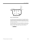
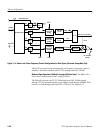
Phase error information from DC through a few hundred kHz is passed through
U606 and switch U700D (when phase lock is invoked) to error amplifier U713.
The output of U713 is applied to the FM coil through R714. When phase lock is
invoked by setting PLLCON to high, U700D is closed and U700C is opened,
closing the outer loop. Nominally, the loop bandwidth is set to 20 kHz. It may
vary considerably from this value due to frequency dependent variations in the
output level and slope of the phase gate. R709 provides for a known drift
direction of the 1st LO tuning when the loop is first closed, but the initial
frequency is away from lock. The instrument firmware purposely sets up a
significant frequency offset in the direction that allows the loop to drift into lock,
as a way of dealing with uncertainties in starting conditions.
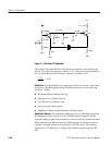
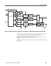
The outer loop has a holding range of approximately ±2.5 MHz before U713
saturates. U650A and U650B form a window comparator that generates logic
signals (either INCR MAIN or DCR MAIN) when the loop approaches a range
limit so that the microprocessor can take corrective action (for example,
changing the main coil current in the appropriate direction to recenter the loop).
1
st
LO Phase Lock Loop
(Outer Loop) and Beat
Note Processor