


Adjustment Procedures
2715 Spectrum Analyzer Service Manual
5-25
d. Adjust R431 on the Log board for a DC level of 20 mV ±2mVatTP9.
e. Adjust R500 on the Log board to position the trace at the bottom
graticule line.
f. Reconnect the 10 MHz/--10 dBm signal to J190 on the Log board
through the 10 dB and 1 dB Step Attenuators. Set the attenuators for
0 dB attenuation (no external attenuation).
g. Adjust R526 on the Log board to position the trace at the top graticule
line.
h. Repeat parts (3) through (7) until both top of screen and bottom of
screen alignment are satisfied.
i. Add 6 dB of attenuation to the input signal.
j. Check that the trace is within 2 minor divisions of the fourth graticule
line from top of screen.
k. Add another 6 dB of attenuation to the input signal.
l. Check that the trace is within 2 minor divisions of the sixth graticule line
from top of screen.
m. Add another 6 dB of attenuation to the input signal.
n. Check that the trace is within 2 minor divisions of the seventh graticule
line from top of screen.
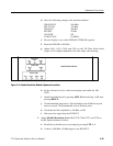
5. Adjust RF Gain (R200 on the RF Mother board, R170 on the Reference
Oscillator board) as follows:
a. Recall factory default power up settings by pressing UTlL 1 1.
b. Select the following settings on the Spectrum Analyzer:
FREQUENCY 100 MHz
SPAN/DIV 2 MHz
REFERENCE LEVEL --30 dBm
RESOLUTION BW 5 MHz
VIDEO FILTER On
VERT SCALE LIN
c. Connect a 100 MHz signal to the RF INPUT as follows:
H All instruments except Option 50 - Connect a 50 -- 75 Ω min loss
pad to the Power Meter power head. Connect the min loss pad to the
Signal Generator input. Set the amplitude of a 100 MHz signal from
the Signal Generator and cable combination to --30.2 dBm, then
connect the 100 MHz signal to the RF INPUT.