


Maintenance
6-16
2715 Spectrum Analyzer Service Manual
NOTE. Disconnect the instrument from its power source before replacing or
soldering components.
Extreme caution must be used when removing or replacing components, because
the instrument contains several multi layer circuit boards. Excess heat from the
soldering iron and bent component leads may pull the plating out of the hole.
Some circuit boards do contain leaded components. To remove the component
leads, use a 15 W (or less) pencil type soldering iron. Straighten the leads on the
back side of the board; when the solder melts, gently pull the soldered lead
through the hole. A desoldering tool should be used to remove the old solder.
Use a desoldering tool that has a low build up of static charge, such as Silverstat
Soldapullt desoldering tool, when unsoldering integrated circuits or transistors.
Transistor and Integrated Circuit Configurations. Lead identification for transistors
and integrated circuits is readily available from manufacturer’s data books.
Integrated circuit pin outs for Vcc and ground are shown with a box on the
schematic diagram.
Diode Color Code. The cathode of each glass encased diode is indicated by a
stripe, a series of stripes, or a dot. Some diodes have a diode symbol printed on
one side.
Resistor Values. Surface mounted resistors have no visible identification.
However, the value can be measured with a meter. Other types of resistors (such
as composition, metal film, tapped, thick film resistor network package, and
plate) are also used. The value is either color coded in accordance with the EIA
color code or printed on the body of the component.
Capacitor Marking. Surface mounted capacitors (chip capacitors) have no visible
markings. The capacitance value, voltage rating, and polarity of electrolytic
capacitors are marked on the side of the component body. The ceramic tubular
capacitors and feed through capacitors are color coded in picofarads.
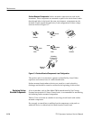
Multiple Terminal (Harmonica) Connectors. Some intercircuit connections are
made through square pin connectors that are mounted in a harmonica type
holder. If one of the pins must be replaced, all the pins at that location must be
replaced as a set. Most ribbon cable connectors are key6ed. Exceptions are: two
pin connectors, the three pin connector at the back of the Log board, and the 50
pin connector between the Microprocessor, Display Storage, and Digital Options
boards. The key location on the circuit board is identified by a missing pin.
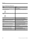
Soldering Techniques