


Specifications
2715 Spectrum Analyzer Service Manual
1-19
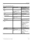
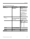
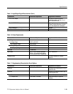
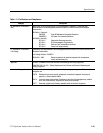
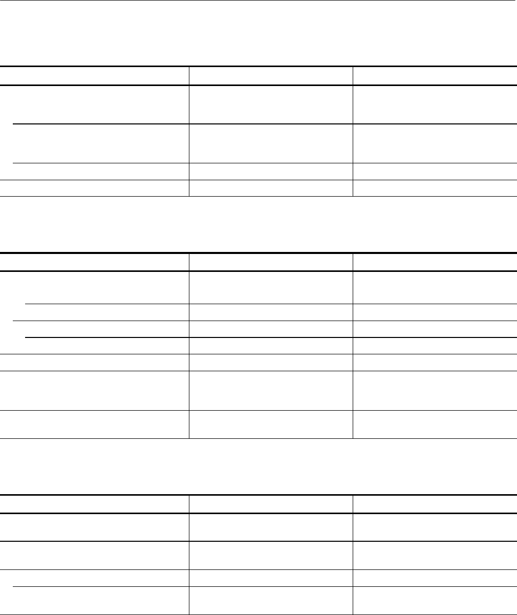
Table 1- 5: Input/Output Signal Charact eristics (Cont.)
Characteri stic Supplemental InformationPerformance Requirement
Pin 11: VLVL Output DC output to Option 05 (External
Tracki ng Generator); typically ᐔ9.5 V
with TG level set to ON.
Pin 12: SWPSLOPE Output Negative going ramp output to Option 05
(External Tracking Generator); typically
ᐔ5 V with analyzer set to max span.
Pins 13 through 15 Not used
Digital Communications Port (J104) RS-232 or GPIB connector
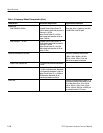
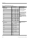
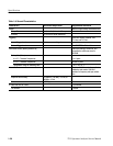
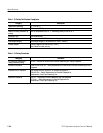
Table 1- 6: Power Requirements
Characteristic Performance Requirement Supplemental Information
Input Voltage
Line Voltage Range 90 VAC to 250 VAC
Line Frequency Range 48 Hz to 63 Hz
Line Voltage Range 90 VAC to 132 VAC
Line Frequency Range 48 Hz to 440 Hz
Line Fuse 2ASlow-Blow
Input Power 90 W (1.2 A) for standard instrument
105 W (1.4 A) m aximum with options
(115 W maximum at 90 V and 440 Hz)
At 115 V and 60 Hz
Leakage Current 3.5 mA
RMS
maximum or 5 mA
peak
maximum
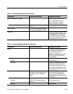
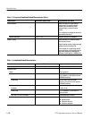
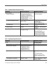
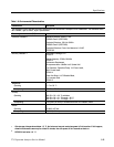
Table 1- 7: Supplementary Characteristics Due to Options
Characteristic Performance Requirement Supplemental Information
Option 03 Provides a GPIB interface port at J104 to
replace RS-232
Option 08 Provides a RS-232 serial interface port at
J104 to replace GPIB
Option 15 Adda1
st
LO output
1
st
LO Output Level ≥+48.8 dBmV (≥0.0 dBm) At spectrum analyzer frequencies
≥100 kHz