Adjustment Procedures
2715 Spectrum Analyzer Service Manual
5-21
Use the following procedure to adjust the Log Board.
H Test equipment required:
Signal Generator (Marconi 2022)
10 dB and 1 dB S tep Attenuators
Multimeter (DMM)
RF Cable, BNC to SMB
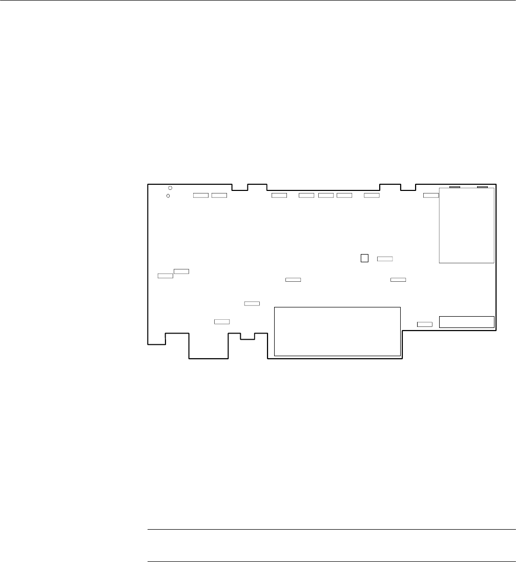
Refer to Figure 5--6 for all adjustment locations on the Log board.
R160
R172
Log Board
TP8
TP9
C357
R153R142R141R134R118R114
R770
R466
R431
R501
R500
R526
R622
R464
C280 C392
Figure 5- 6: Log Board Adjustment and Test Point Locations
1. Adjust 10 dB/div, 5 dB/div, and 1 dB/div Log Match (R622 on the Log
board)
a. Recall factory default power up settings by pressing UTlL 1 1. Recall
default amplitude normalizations by pressing UTIL5529Y.Pressany
menu button to exit the menu.
b. Set R160 and R172 on the Log board fully counterclockwise.
NOTE. Changing the adjustment of either R160 or R172 requires that you
complete the Amplitude Flatness Adjustment Procedure on Page 5--52.
c. Disconnect P 190 from the Log board, and use the BNC to SMB cable to
connect a 10 MHz/--10 dBm signal to J190 through the 10 dB and
1 dB Step Attenuators. Set the attenuators for 0 dB attenuation.
Log Board Adjustment
