Adjustment Procedures
5-42
2715 Spectrum Analyzer Service Manual
h. Connect the oscilloscope test probe to TP 8 on the S weep board.
i. Press Util523Utilto stop the sweep at center screen.
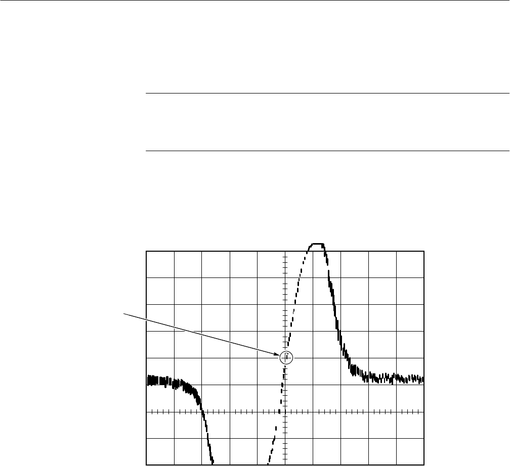
NOTE. Refer to Figure 5--16. This is a representation of what the waveform at TP8
would look like if the analyzer was sweeping. The scope will be indicating a DC
level. The point indicated in Figur e 5--16 will need to be adjusted to 0.7 VDC by
adjusting C781.
j. Adjust C781 through its range to locate the midpoint of the waveform
between its extremes. When it has been determined that C781 is adjusted
to this point, set C781 for 0.7 VDC. Change the oscilloscope to 0.1
V/Div to increase the accuracy of the adjustment.
Set this point for
0.7 VDC with C781
Figure 5- 16: Typical FM Adjustment Waveform
k. Remove the probe from TP8 and press AUTO SWEEP twice to restart
the sweep.
l. Connect a FM video signal to the RF IN.
m. Tune the Spectrum Analyzer to an FM visual carrier.
n. Set FM (Satellite) video signal parameters by pressing DEMOD 9 and
selecting S ATELLITE VIDEO DETECT MODE, NEGATIVE SYNC
POLARITY, and POSITIVE VIDEO POLARITY. Press any menu
button to exit the menu.


