Theory of Operation
3-14
2715 Spectrum Analyzer Service Manual
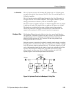
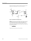
110 MHz Bandpass Filter. This filter is a 5th order, shunt resonator Butterworth
filter.
3rd Mixer. U665 and its associated circuitry make up the 3rd mixer.
Output Amplifier. This IF amplifier consists of a common emitter transistor
(Q670) with both series and parallel feedback. The 1:1 transformer (T670)
provides lower output impedance for better intermodulation distortion perfor-
mance. The resistive attenuator at the output is used to match the load to the
variable resolution. It also provides some high frequency roll off.
1
st
LO Interface, 1
st
LO, and 1
st
LO Buffer Amplifier
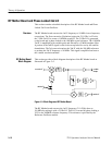
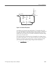
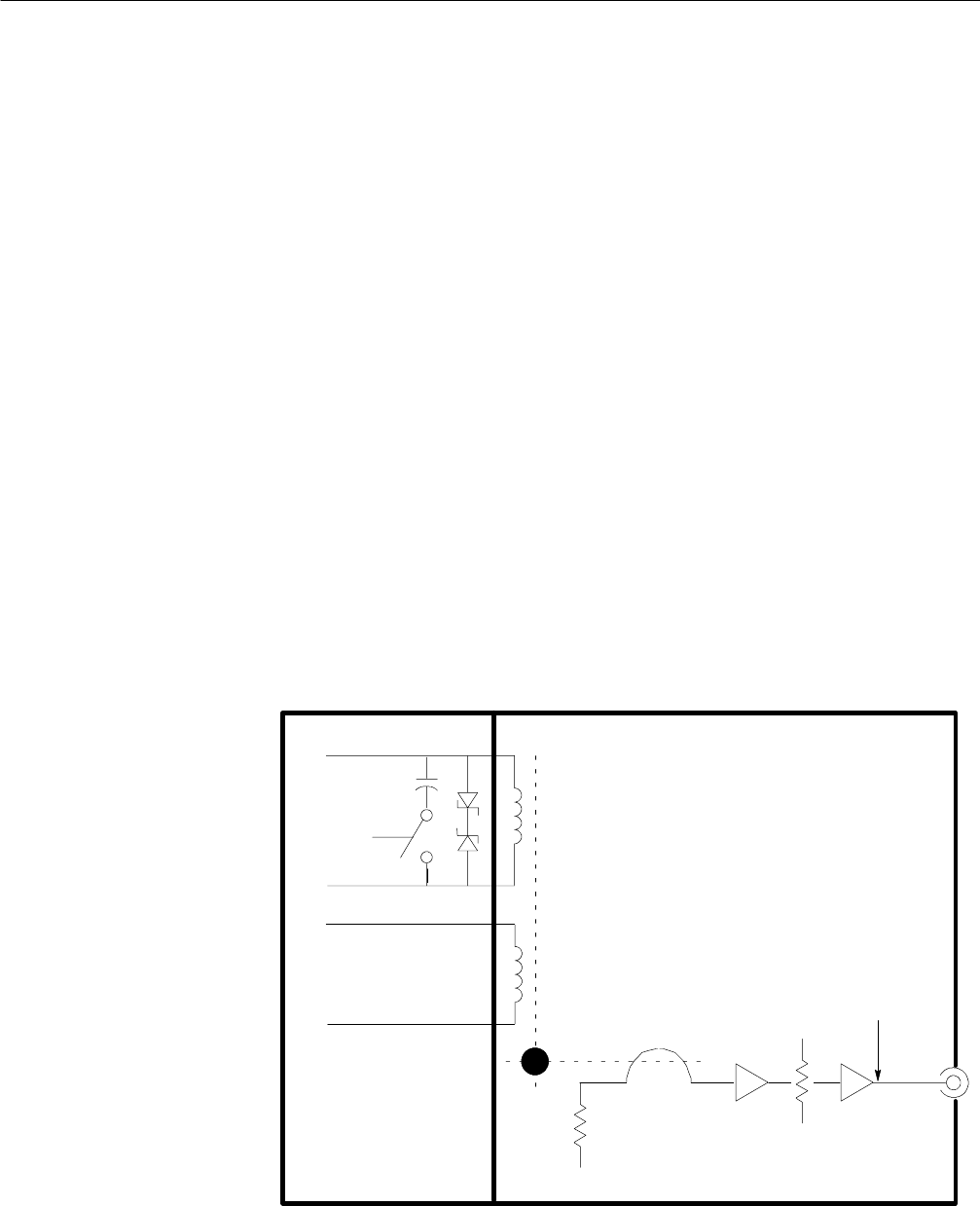
This section contains a detailed description of the 1st LO Interface, 1st LO and
1st Buffer Amplifier.
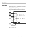
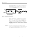
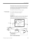
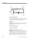
The 1st LO has a tuning range of 2.11 to 3. 91 GHz (2.11 to 4.26 GHz for Option
50 and 75). The oscillator assembly includes the interface circuit board that
couples operating and tuning voltages from the Center Frequency Control board.
Two Zener diodes on the Interface board clamp transient voltages from the main
coil. See Figure 3--6.
−V
1st LO1st LO Interface
+Main
−Main
+FM
SWP Main
−FM
YIG Sphere
1st LO Out to 1st LO
Buffer Amplifier
Figure 3- 6: 1st LO Interface and 1st LO Diagram
1
st
LO Interface
and 1
st
LO


