


Adjustment Procedures
5-12
2715 Spectrum Analyzer Service Manual
30. Adjust R705 (GEO) on the Power S upply board and VERT POS (R6) at the
rear panel for the straightest trace possible at the top edge of the screen.
31. Adjust R910 (VERT GAIN) on the Power Supply board to place the bottom
of the trace at the bottom graticule line.
32. Disable the DEFLECTION AMP CAL signal by pressing UTIL521and
enable SWEEP CAL by pressing 3. Press any menu button to exit the menu.
33. Adjust HORIZ POS (R5) on the rear panel to position the CRT beam to the
center vertical graticule line.
34. Move the beam at the right edge of the graticule by pressing SWEEP ↑ three
times.
35. Adjust R900 (HOR GAIN) on the Power Supply board to place the beam at
the right edge of the graticule.
Use this procedure to adjust R290 and R280 on the Sweep board. HORIZ POS
(R5) on the rear panel. R901 on the Power Supply board.
H Test equipment required:
Multimeter (DMM)
1. Recall default power up settings by pressing UTIL 1 1.
2. Disable the DISPLAY STORAGE, and center the beam by pressing
UTIL523. Press any menu button to exit the menu.
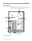
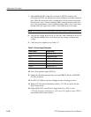
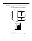
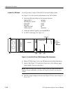
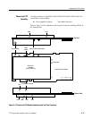
3. Monitor TP 2 with the Multimeter. See Figure 5--1 for the location of TP2.
4. Adjust R290 on the Sweep board (Figure 5--1) for 0.0 V ±2mVatTP2.
5. Adjust HORIZ POS (R5) on the rear panel to position the CRT beam to the
center vertical graticule line.
6. Move the beam at the right edge of the graticule by pressing SWEEP ↑ three
times.
7. Adjust R280 on the Sweep board (Figure 5--1) for --1.190 V at TP2.
8. Adjust R901 on the Power Supply board (Figure 5--1) to place the beam at
the right edge of the graticule.
9. Disable the Sweep Cal signal by pressing UTIL523. Exit the menu by
pressing any menu button. Press SWEEP AUTO to enable the sweep.
Sweep and Horizontal
Deflection Amplifier