Performance Verification
2715 Spectrum Analyzer Service Manual
4-11
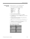
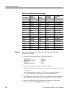
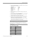
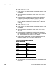
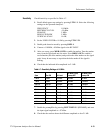
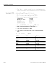
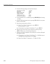
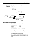
1. Recall default power up settings by pressing UTIL 1 1. Select the following
settings on the Spectrum Analyzer:
FREQUENCY 110 MHz
REFERENCE LEVEL --20 dBm
SPAN/DIV 1 kHz
RESOLUTION BW AUTO
VID FLTR On
VERTICAL SCALE 1 dB/
MARKER On
2. Connect a 110 MHz signal to the RF INPUT through the 10 dB and 1 dB
step attenuators.
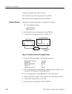
3. Set the attenuators for 0 dB attenuation, set the amplitude of the input signal
for full screen deflection, and press PEAK FIND.
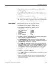
4. Change the Vertical Scale to 10dB/ and increase the attenuation to 10 dB.
Check that the Marker readout changes by 10 dB ±1dB.
5. Continue to increase the attenuation in 10 dB steps to a total attenuation of
80 dB (See Note below) while checking that the Marker readout changes
10 dB ±1 dB for each 10 dB change in attenuation.
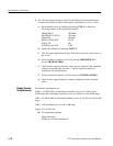
Check also that the cumulative error does not exceed ±2 dB over the 70 dB
range and the total error (80 dB) does not exceed ±4dB.
NOTE. In 10 dB/Div the noise floor limits the s ignal range that can be resolved. As
the Resolution Bandwidth is decreased, higher resolution is possible. Table 4 --5
indicates this limit for each RES BW setting. Refer to step 14 on page 4--12
When making this check, press PEAK FIND as necessary, to keep the marker at
the top of the signal.
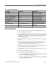
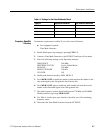
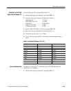
Table 4- 5: Maximum Range in 10 dB/Div
RES BW dB Down From Top of Screen
5MHz 40 dB
1MHz 40 dB
300 kHz 50 dB
100 kHz 50 dB
30 kHz 60 dB
10 kHz 60 dB
3 kHz 80 dB
1 kHz 80 dB
300 Hz 80 dB


