


Adjustment Procedures
5-6
2715 Spectrum Analyzer Service Manual
Adjustments
Use the following procedures to bring the 2715 operating parameters within the
tolerances specified in Section 1: Specifications.
Two procedures are provided for adjusting the Power Supply and Deflection
circuits. Check the serial number of your instrument then perform one of the two
procedures given below.
Instrument with serial number below B030000
. Adjust R639, R680, R703, R704,
R705, R900, and R930 on the Power Supply board and R6, R7, and R110 on the
rear panel.
H Test equipment required:
Voltage Variable Isolation Transformer
Test Oscilloscope with Probes
Multimeter (DMM)
High Voltage Probe (X1000)
WARNING. Use an isolation transformer when working on the Power Supply.
The transformer must have a three wire input and output connector with ground
through the input and output. Stancor GIS21000 is an example of a suitable
transformer.
Hazardous line potential exists on the Power Supply board at all times the
instrument power cord is connected. If it becomes necessary to remove the shield
on the bottom of the Power Supply board, use extreme caution when handling
the instrument.
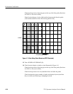
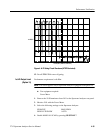
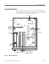
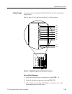
Refer to Figure 5--1 for the location of most adjustments and test points.
1. Connect an Isolation T ransformer in line with the Spectrum Analyzer power
input and the AC line voltage source of 90 to 250 VAC.
2. Apply power to the Spectrum Analyzer and turn on the graticule lights
(DSPL 6).
3. Adjust R937 (+5 V ADJ) on the Power Supply board for +5.0 VDC at the
+5 V test point.
Power Supply and
Deflection