Specifications
1-18
2715 Spectrum Analyzer Service Manual
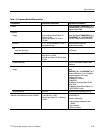
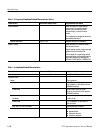
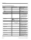
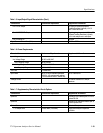
Table 1- 5: Input/Output Signal Charact eristics (Cont.)
Characteri stic Supplemental InformationPerformance Requirement
Ext Trig (J102) BNC connector, 10 kΩ, DC coupled for
external trigger signals
Volt age Range
Minimum Typically at least 100 mV
peak
,15Hzto
1MHz
Maximum 50 V (DC + peak AC)
Pulse Width 0.1 s minimum
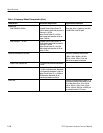
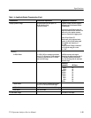
Accessory Connector (J103) DB-15 f emale connector
Pin 1: External Video Input Typically 100 ohm, DC coupled, 0 -
50 kHz, 0 -- 1.6 V (200 mV/div) signal
input for vertical deflection of the CRT
beam. The signal is processed t hrough
the video filters and the 1 dB, 5 dB, and
10 dB scale factor circuits on the Log
board. Display storage may be by-
passed.
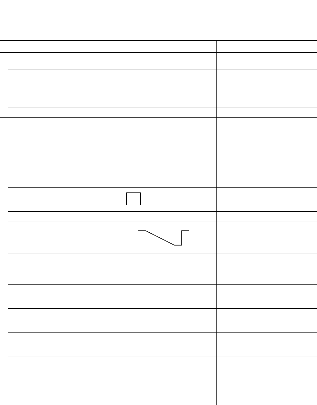
Pin 2: Sweep Gate
+2.0 V minimum (high)
0.8 V maximum (low)
TTL-compatible signal that goes to a
logic high l evel while the CRT beam is
sweeping.
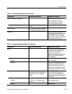
Pin 3: Chassis and Signal Ground
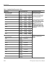
Pin 4: Sweep Output
-- 1 . 3 V
+1.3 V
Provides a nominal +1.3 V to --1.3 V
negative-goi ng ramp, proportional to the
horizontal sweep (output impedance
≤50 Ω).
Pin 5: Log Video Output Provides 0 V to +1.6 V of video signal,
inversely proportional to the vertical
display amplitude. 0 V is t he top of the
screen. Impedance is 1 kΩ.
Pin 6: CLK0 Output Clock output to Option 05 (External
Tracki ng Generator). CMOS logic levels
typically +3.5 V high, +1.5 V low.
Pin 7: Data I Input Data input from Option 05 (External
Tracki ng Generator). Typically +5 V high,
+0.1 V low.
Pin 8: Data O Output Data output to Option 05 (External
Tracki ng Generator). CMOS logic levels,
typically +3.5 V high, +1.5 V low.
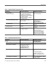
Pin 9: ~EXTGLATCH Logic output to Option 05 (External
Tracki ng Generator). CMOS logic levels,
typically +3.5 V high, +1.5 V low.
Pin 10: 26.38 MHz I nput Input from Option 05 (External Tracking
Generator); typically a 0.5 V
p-p
sine wave
centered at +3.7 VDC.


