Theory of Operation
2715 Spectrum Analyzer Service Manual
3-9
Circuit Description
The following sections provide detailed circuit descriptions and is arranged to
follow the input signal flow. While reading these descriptions, refer to the
corresponding diagrams in Section 9: Diagrams.
Attenuator and 1
st
Converter
The Attenuator and 1st Converter signal path consists of the following parts:
H Step Attenuator
H 1.8 GHz Low Pass Filter (2.2 GHz Low Pass Filter for Option 50 and Option
75)
H Mixer
H 4.5 GHz Low Pass Filter
H 2110 MHz Bandpass Filter
The Spectrum Analyzer input frequency range is 9 kHz to 1.8 GHz (2.15 GHz
for Option 50 and Option 75). The low end of the frequency range is determined
by a capacitor on the Attenuator board, the narrowest resolution filter in the
Variable Resolution assembly, and FM characteristics of the 1st LO (YIG
Oscillator).
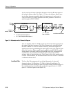
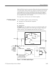
The signal comes in at the front panel RF INPUT connector. The 75 Ω RF
INPUT connector is connected to a 0 to 50 dB step attenuator, capable of
stepping from 0 to 50 dB in 2 dB steps. The Attenuator consists of relay
controlled pads of 2, 4, 8, 16, and 20 dB. The instrument firmware controls the
relays to provide the necessary attenuation to maintain a calibrated reference
level.
Step Attenuator


