Performance Verification
4-22
2715 Spectrum Analyzer Service Manual
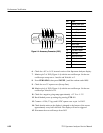
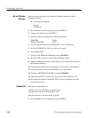
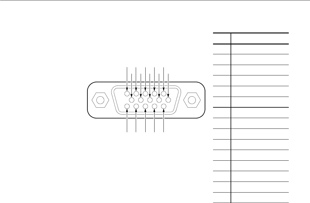
Pin Signal
1 External Video Input
2 Sweep Gate
3 Chassis/Signal Ground
4 Sweep Ramp
5 Video Out
6 CLK0 Input
7 DATAI Output
8 DATAO Input
9 ᇓDOLATCH Input
10 26.38 MHz Output
11 VLVL Input
12 SWPSLOPE Input
13 Not Used
14 Not Used
15 Not Used
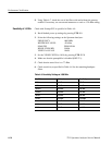
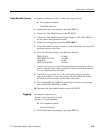
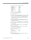
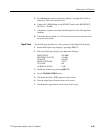
6. Check for a 0 V to 1.6 V inverted version of the Spectrum Analyzer display.
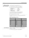
7. Monitor pin 2 of J103 (Figure 4--4) with the test oscilloscope. Set the test
oscilloscope sweep rate to 1 ms/div and Volts/div to 2.
8. Press ZERO SPAN,thenpressSWEEP ↓ until the readout reads 1MS/.
9. Check for an ≈5 V square wave (Sweep Gate).
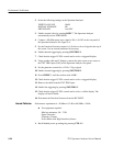
10. Monitor pin 4 of J103 (Figure 4--4) with the test oscilloscope. Set the test
oscilloscope Volts/div to 0.5.
11. Check for a negative going ramp approximately +1.3 V to --1.3 V.
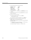
12. Recall default power up settings by pressing UTIL 1 1.
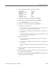
13. Connect a 15 Hz, 2 Vp-p, and 0 VDC square wave to pin 1 of J103.
14. Check that the noise on the display is clamped to the bottom of the screen
approximately every half a division. The display will not be triggered.
15. Disconnect the test oscilloscope from J103.
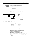
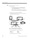
1112131415
12345
678910
Figure 4- 4: Accessory Connector (J103)


