


Specifications
2715 Spectrum Analyzer Service Manual
1-17
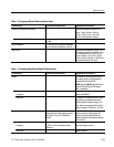
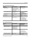
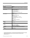
Table 1- 4: Amplitude -Related Characteristics (Cont.)
Characteri stic Supplemental InformationPerform ance Requirement
Spurious Responses
Residual (no input signal) All except Option 50 and Option 75:
≤ --51 dBmV (≤--100 dBm) except at
1780 MHz where the spurious response is
≤--41 dBmV (≤--90 dBm).
Option 50 and Option 75: ≤--26 dBmV
(≤--75 dBm) at 2.0 GHz.
With 0 dB RF att enuation
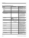
3
rd
Order IM (Intermodulat ion) Products All except Option 50 and Option 75: ≤-- 7 0
dBcupto1.8GHz
From any two on-screen signals within
any frequency span
Option 50 and Option 75:
Typically ≤--65 dBc at 2.15 GHz
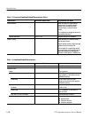
Zero Frequency Spur ≤+39 dBmV (≤--10 dBm) Referenced to input with 0 dB RF
attenuation
2
nd
Harmonic Distortion ≤--66 dBc Measured with 1
st
mixer input level of
≤+9 dBmV
LO (Local Oscillator) Emission All except Option 50 and Opt ion 75: ≤-- 7 0
≤--21 dBmV (≤--70 dBm)
With 0 dB RF att enuation and preamp
off.
Option 50 and Option 75:
When frequency is below 90 MHz:
Typically <+29 dBmV (–20 dBm)
When frequency is above 350 MHz:
Typically ≤--21 dBmV (≤--70 dBm)
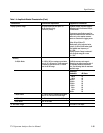
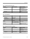
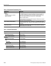
Table 1- 5: Input/Output Signal Charact eristics
Characteristic Performance Requirement Supplemental Information
RF Input Type F male connector or
type N female connector
VSWR with RF Attenuation ≥10 dB 1.5:1 maximum Checked to 1 GHz
VSWR with 0 dB RF At tenuation All except Option 50 and Option 75:
2:1maximumupto1GHz
3.5:1 maximum up to 1.8 GHz
Option 50 and Option 75:
4:1maximumupto2.15GHz
Maximum Safe Input +70 dBmV (0.1 W or 2.2 V) continuous
peak
100 VDC blocking capacitor
Caution: Do not apply more than
100 VDC or 100V peak AC to the RF
Input
1 dB Compression Point (minimum) +34 dBmV (--15 dBm) With no RF Attenuation and 1
st
mixer at
+19 dBmV (--30 dBm)