


Theory of Operation
2715 Spectrum Analyzer Service Manual
3-45
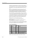
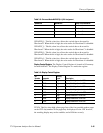
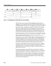
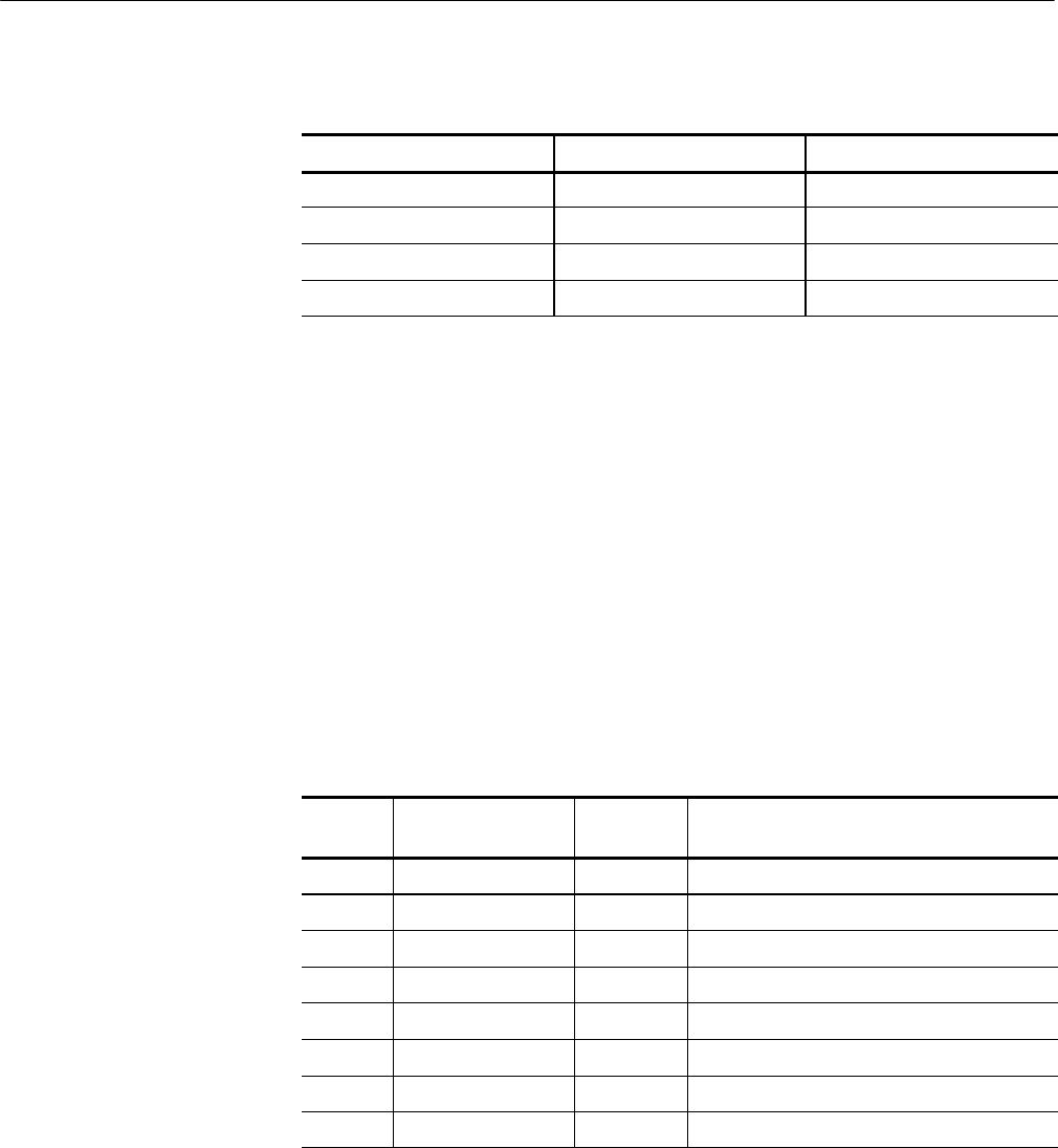
Table 3- 8:
Enhanced Mode MKRWFM[1..0] Bit Assignment
MKRWFM3
MKRWFM2 Marker 2 on Waveform...
0 0 Waveform A
0 1 Waveform B
1 0 Waveform C
1 1 Waveform D
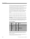
UPDATED_L. This bit, when low, allows the vertical data to be stored in
Waveform D. When the bit is high, the write strobe for Waveform D is disabled.
UPDATEC_L. This bit, when low, allows the vertical data to be stored in
Waveform C. When the bit is high, the write strobe for Waveform C is disabled.
UPDATEB_L. This bit, when low, allows the vertical data to be stored in
Waveform B. When the bit is high, the write strobe for Waveform B is disabled.
UPDATEA_L. This bit, when low, allows the vertical data to be stored in
Waveform A. When the bit is high, the write strobe for Waveform A is disabled.
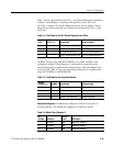
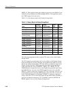
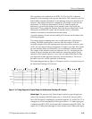
Display Control Register. The Display Control Register is located at I/O memory
location 0x0FA02. The Display Control Register is a read/write register.
Table 3- 9: Display Contr ol Register
Bit
Number
Mnemonic
Activity
Level
Description
7 TEXT4 High Display Text Page 4 on the CRT
6 TEXT3 High Display Text Page 3 on the CRT
5 TEXT2 High Display Text Page 2 on the CRT
4 TEXT1 High Display Text Page 1 (readouts) on the CRT
3 DISPD High Display Waveform D on the CRT
2 DISPC High Display Waveform C on the CRT
1 DISPB High Display Waveform B on the CRT
0 DISPA High Display Waveform A on the CRT
TEXT4. This bit, when high, places page four of the four possible readout pages
on the CRT. Any number of text pages may be displayed on the CRT however,
the resulting display may not be readable, and will flicker severely.