Theory of Operation
3-40
2715 Spectrum Analyzer Service Manual
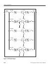
Immediately following the Video Filters is the Scale Factor amplifier. The gain
of the Scale Factor amplifier can be set to 1.1, 2.2, 5.5, or 11 corresponding to
10 dB/div, 5 dB/div, 2 dB/div, or 1 dB/div. The linear function is done with the
gain set to 1.1.
The AD834 (U350) is a four quadrant multiplier that is used as a quadrature
detector for demodulation of FM signals. The audio output is sent to the audio
amplifier selector and to the video input selector.
The limited output of one of the log cells is used to drive an isolation buffer
(U630A). This signal is used to drive the period counter on the Microprocessor
board for frequency measurements.
The TDA1013A is used as the audio amplifier for monitoring purposes, and as a
means of providing feedback to the user from the microprocessor.
Microprocessor audio appearing at pin 22 of J7 is used to provide feedback to
the operator for push button clicks and out of range or uncalibrated conditions.
This signal is also used to provide a signal for calibrating the video amplifier and
display storage. The sweep triggers are also tested by this signal.
At power on, the system reset line S YSRST-- on pin 4 of J7 goes low until the
Microprocessor resets it. During this time, the control latch’s output enable line
is held false and the outputs are in a high impedance state. This is used only by
the mute bit. The pull up resistor will force a mute condition during this time,
thus disallowing any extraneous noise from the speaker.
Display Storage
The Display Storage board digitizes both vertical (LOGVID) and horizontal
(SWP) signals and places this digitized information in nonvolatile RAM
(NVRAM). Various state machines on the board then take this digitized data
from the NVRAM and generate the horizontal and vertical signals which are sent
to the deflection circuitry on the Power Supply board. In addition to displaying
the digitized data, the Display Storage board also is used to display the readouts
and place markers on the CRT.
The major features of the Display Storage board are:
H Digitize the LOGVID signal from the Log Board (8 bits)
H Digitally track the SWP signal from the Sweep Board (9 bits)
H Acquire and store up to four waveforms in RAM
FM Detector
Period Counter Signal
Audio Amplifier
Video Amplitude
Calibrator
System Reset


