


2715 Spectrum Analyzer Service Manual
3-1
Theory of Operation
This section describes the 2715 circuitry. The section begins with a functional
description of the major circuit blocks. This is followed by more detailed
descriptions of the circuitry within each block. While reading these descriptions,
refer to the corresponding diagrams in Section 9: Diagrams.
Block Diagram Description
The Spectrum Analyzer block diagram contains the following major blocks:
H Attenuator and Low Pass Filter
H 1st Converter
H 2nd Converter
H RF Mother Board (3rd Converter)
H VR (Variable Resolution Module)
H Log Amplifier
H Display Storage board
H Center Frequency Control
H 1st LO Buffer
H Microprocessor
H Sweep
H Power Supply (Deflection)
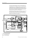
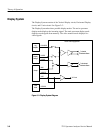
This is a block diagram description of the Spectrum Analyzer. While reading this
description, refer to Figure 3--1.
NOTE. The power levels noted in the block diagram between the input and the
Log Amplifier assume a --30 dBm (+18.8 dBmV) input level.
The block diagram shows how the major sections in the instrument relate. It also
shows the paths of most major signals. Not explicitly shown are the interconnec-
tions between the Power Supply and the circuit blocks, interconnections between
the Sweep board and other major circuit blocks, and interconnections between
the Deflection System and other circuit blocks. (The Deflection System is
located on the Power Supply board.)