Maintenance
2715 Spectrum Analyzer Service Manual
6-23
Use the following procedure to replace the RF Deck assembly:
NOTE. Replacement of this assembly requires completion of the .Amplitude
Flatness Adjustment Procedure on Page 5--52.
1. Remove the instrument from its cabinet (see Removing the Instrument from
its Cabinet on Page 6--17).
2. Remove the Front Panel assembly (see Replacing the Front Panel Assembly
on Page 6--21).
3. Remove the circuit board retainer.
4. Remove the Variable Resolution module.
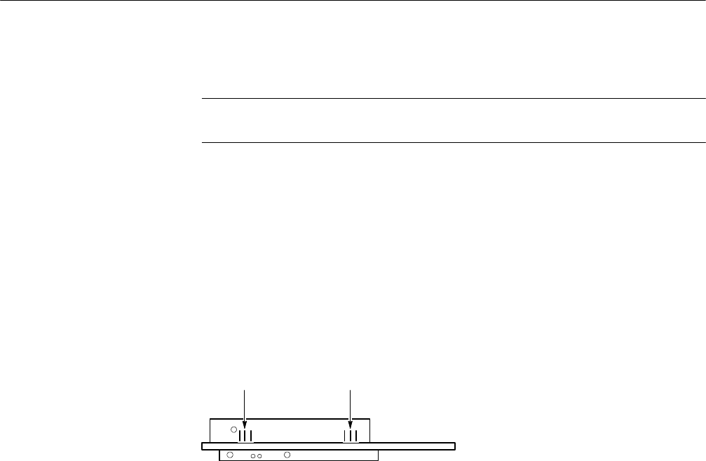
5. Disconnect P510 and P550 (Figure 6--7) from the Phase Lock assembly.
Bottom View of Phase Lock Assembly
J510 J550
Figure 6- 7: Locations of J510 and J550 on the Phase Lock Assembly
6. Disconnect P100 and P200 (Figure 6--8) from the Attenuator assembly.
7. Disconnect P400, P410, P565, P670 (Figure 6--8) from the RF Mother board
assembly.
8. Disconnect P430 and P460 (and P300 if Option 04 or Option 15 is installed)
from the 1st LO Buffer Amp assembly (Figure 6--8).
9. Remove the seven screws and two nuts shown in F igure 6--9.
10. Loosen the two nuts shown in Figure 6--9.
11. With the instrument facing you, carefully raise the rear part of the RF deck
and swing it to the left while pulling it backwards.
Replace the RF deck by reversing the removal procedure.
Replacing the RF Deck


