Maintenance
6-34
2715 Spectrum Analyzer Service Manual
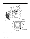
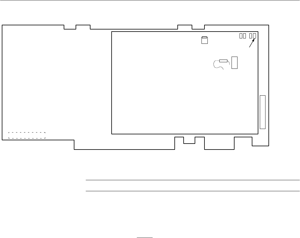
Interconnect plug to J11 on Power
Supply Board is on opposite side
R620
R602
U713
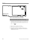
Figure 6- 13: Location of R602 on the Phase Lock CFC Board
NOTE. If the beat note frequency is above 50 kHz, it w ill not be visible.
6. If the amplitude is greater than 60 mV, pick a lower value for R602. If the
amplitude is lower than 40 mV, pick a higher value. See Figure 6--13 for the
location of R602. The following formula helps in picking a resistor value:
R602 = 5620
60 mV
Vp–p
Ω
7. Replace the shield on the Phase Lock CFC board.
8. Enable frequency normalizations by pressing UTIL 3 1.
9. After frequency normalizations are complete, set the FREQUENCY to
100 MHz and enable the calibrator signal (INPUT 9). There should be a
100 MHz signal at center screen.


