Theory of Operation
3-38
2715 Spectrum Analyzer Service Manual
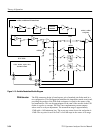
Log Amplifier
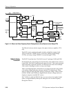
The Log Amplifier system is a high performance, intermediate amplifier system
that provides display laws of linear detection and logarithmic detection of the
incoming signal. The log display has scale factors of 10 dB/div, 5 dB/div, and
1 dB/div. The linear mode has the ability to magnify the top portion of the
waveform to enhance the measurement capability. The module also contains an
FM detector, which, when used with the built in audio amplifier, can be used to
monitor the modulated input signal for enhanced signal identification. The audio
amplifier can also be used to monitor the output of the displayed waveform
regardless of the video source. There is an alternate audio input for the push
button clicks generated by the system controller. This audio signal is also used
for the vertical amplitude reference, to check the sweep speed, and for internal
triggers. An amplitude limited output is available for the period counter for
determining the actual frequency of the signal present in the IF system. External
video inputs are provided for the use of external detectors and the rear panel. A
provision is made for clamping the display when the 1st LO is tuned out-of-
band. Frequency dependent amplitude (flatness) correction is also performed on
this board.
The Log Amplifier system is configured by using a 4.5 by 8.75 circuit board
mounted in the card cage. The Microprocessor interface is through three 8 bit
shift registers.
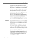
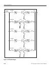
The signal level at the Log Amplifier board (J190) for full screen deflection is
--10 dBm. The first stage of the Log Amplifier is an amplifier that provides gain
between 18 dB and 24 dB, depending on the frequency of the 1st LO. The
amplifier is adjusted such that the gain is 18 dB at low frequencies and is up to
24 dB at the high end of the frequency range, because the frequency dependent
amplitude error is always greater at the higher frequencies. The feedback is
adjusted by changing the amount of current flowing through PIN diodes CR290
or CR291. The correction voltage, SWPSLOPE, reflects the frequency of the 1st
LO. Provision for a second correction voltage from a future Digital Signal
Processing module is included. This second correction voltage, which provides
an interpolated voltage, will be derived from a flatness table. At present, only
SWPSLOPE is used.
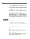
The output of the first stage, a gain slope amplifier, is then fed to a two pole
noise filter to limit the noise to 5 MHz and to provide two more poles of 5 MHz
bandwidth resolution filtering. The output of this filter is then sent to the log
stages through a set of jumpers so the signal can be broken for calibration
purposes and buffer amplifier Q170 (in a common base configuration) to form an
auxiliary IF output.
Hardware
Flatness Error Correction
Noise Filter


