


Theory of Operation
2715 Spectrum Analyzer Service Manual
3-35
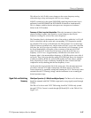
The 10 dB gain step stages incorporate a transformer feedback amplifier. These
stages have approximately 0.5 dB of loss or 9.5 dB of gain, for a net difference
of 10 dB. When the gain step is selected, the signal is routed through the
amplifier for a gain of approximately 11.5 dB. A pad of approximately 1.5 dB is
added to trim the gain down to 10 dB. The signal is then routed through a switch
that has approximately 0.5 dB of loss. When the amplifier is deselected, the
signal is routed around the amplifier, thus preserving noise figure and intercept
point. A total of five step gain stages are used.
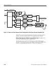
The 1 dB gain step amplifier is the last amplifier before the filter switching tree.
The amplifier is composed of a class AB, three stage, feedback amplifier. The
gain is adjusted in 2 dB steps for a total of 10 dB . The 1 dB steps are done by
shunting part of the signal to ground. This is controlled by Q246, located at the
input of this amplifier. This configuration allows the entire 10 dB gain sequence
to be contained within one step gain stage.
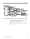
The routing switches are used to route RF signals to various areas. They are
composed of a transistor in heavy saturation that has relatively large charge
storage characteristics. The topology used is a shunt series configuration. These
switches are used on both the input and output of each filter including the
external filter connection.
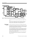
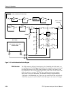
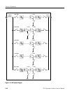
RF Options
The RF Options is a system of additional resolution bandwidth filters that
enhance the measurement capability of the instrument. See Figure 3--16.
10 dB Gain Step Amplifier
1 dB Gain Step Amplifier
Routing Swit ches