Theory of Operation
3-70
2715 Spectrum Analyzer Service Manual
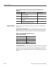
Table 3- 20: Microprocessor Counter Section Connector Signal Names and
Definitions
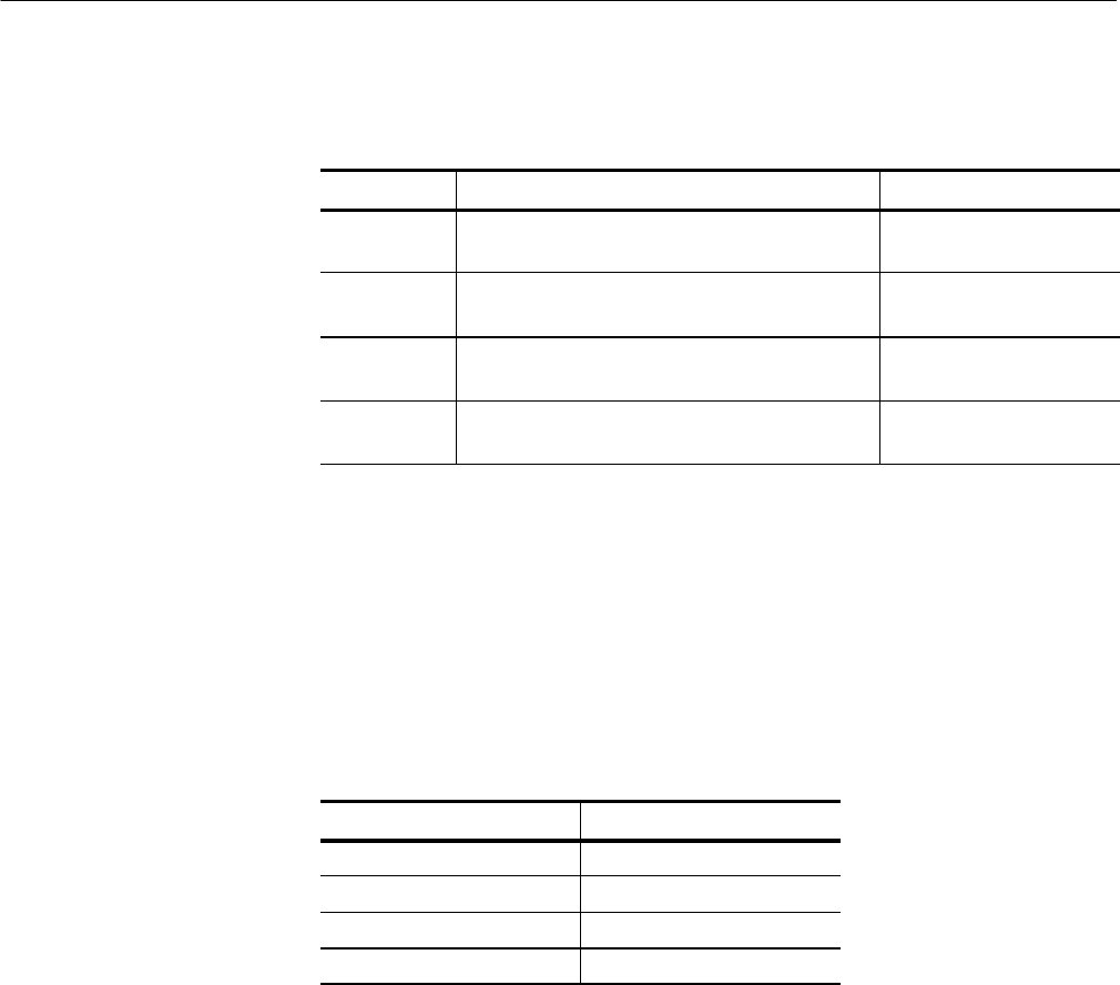
Signal Name Description Source Module
CFC Center Frequency (J180): Signal from the CFC
board to be counted
Center Frequency Control
OPTION Optional Input (J185): Signal from an installed
option to be counted
Installed Option
IF IF Input (J190): IF Signal from the Log board to
be counted
Log Board
100MHZ 100MHZ Calibrator (J195): Reference Signal from
the Reference Oscillator to be counted
Reference Oscillator
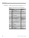
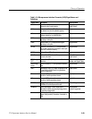
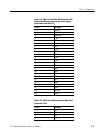
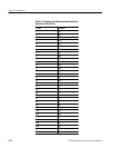
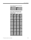
Tables 3 --21 through 3--24 give the pinout for each connector on the Micropro-
cessor board.
Frequency Counter Connectors. There are four SMB connectors that provide the
required signals to the Frequency Counter section of the Microprocessor board.
These four connectors are listed in Figure 3--21 with the associated input name.
Table 3- 21: Connectors and Signal Names for the
Frequency Counter Section
Connector Signal Name
J180 CFC
J185 OPTION
J190 IF
J195 100MHZ
Power Supply Inter face. The Microprocessor board requires only the +5 V supply.
A single 0.1 F capacitor is placed near the power supply pins for each digital
integrated circuit on the board to reduce the noise. In addition there are several
220 F electrolytic capacitors placed near sections of the board that require extra
filtering.
Connector Pinouts


