Theory of Operation
3-62
2715 Spectrum Analyzer Service Manual
CFC
Internal Parallel Bus
8/D
28-Bit
Presettable
Event Counter
U290, U480,
U470
6/A
Legend N/A = N Address
N/D = N Data Lines
Status Buffer
U395, U380A,
U385
Enable/Buffer &
Level Shifters
8/D
Demultiplexer
U530A, U585
8/D
24-Bit
Presettable
Counter
U390, U470
8/D
29-Bit
Presettable
Reference
Counter
U295, U380,
U470
Synchronizer
Synchronizer
Detected Video
Option
IF
100 MHz
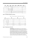
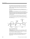
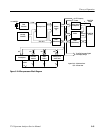
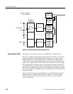
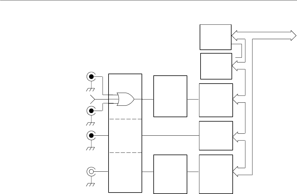
Figure 3- 25: Microprocessor Counter System (CPU)
TheMicroprocessor(CPU)isbasedonan8MHzNECPD70108 (V20).
The V20 is configured in the minimum mode (pin 36 connected to Vcc) using a
demultiplexed bus. In the demultiplexed bus configuration, the address bits
(AD0 through AD7 and A8 through A19) are presented to the address latches
(U440, U450, U465), and the falling edge of ALE (pin 28 of U250) latches the
address lines. Approximately one clock cycle later, the data lines (AD0 through
AD7) become active for either a read or write operation. (Notice that the AD0
through AD7 lines provide both the low order eight bits of address and the eight
bits of data. ) The DIR signal (pin 30 of U250) determines the direction of data
flow on the data lines. This signal is used to set the direction of the bidirectional
data buffer (U460).
Once the address lines have been latched, they are decoded using the Program-
mable Logic Devices (PLDs) U515 and U530, and the 4 to 16 line decoder,
U585. The outputs of these PLDs are used to enable the various peripheral
sections of the board.
Microprocessor (CPU)


