Theory of Operation
3-88
2715 Spectrum Analyzer Service Manual
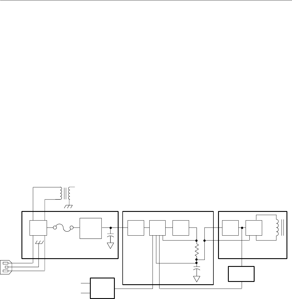
The Power Supply primary circuits consist of the AC Input circuit, a Pulse Width
Modulator (PWM), an Inverter, and a Frequency Lock circuit. See Figure 3--28.
AC Input. Input power is applied through an EMI line filter, a line fuse, an on/off
switch, additional EMI filtering, and a full wave rectifier and storage capacitor.
The line filter prevents power line interference from entering the Power Supply
and also attenuates internally generated signals radiating out the power cord. The
additional EMI filtering attenuates harmonic noise generated in the PWM and
conducted out the power cord. Additional EMI filtering consists of a common
mode choke, line to line capacitors, and line to ground capacitors.
A thermistor, having a negative temperature coefficient, limits current surge at
power up. The surge current drops within several cycles of line input as the
storage capacitor charges. When power is applied, the thermistor limits the line
current until it has had time to warm up. As the line input current heats the
thermistor, the increase in temperature decreases the resistance value of the
thermistor, reducing power loss across the thermistor.
The AC line signal is coupled to the secondary through T110 and is also used in
the trigger circuits as a line trigger source.
Line Trigger
AC Input
Full
Wave
Rectifier
EMI
Filter
Frequency
Lock
OPTO
Isolator/
Regulator
+5 V
+5 V
Delay PWM
Fet
Switch
PWM (Pulse width Modulator) AC Input
PWM
Fet
Switch
Figure 3- 28: Power Supply Primary Block Diagram
PWM Integrated circuit U280, a multifunction PWM IC, is used to drive a
MOSFET switch. The P WM, operating in a single ended mode, sets frequency,
regulates voltage using its internal +5 V reference, allows current limiting, and
provides a slow start up.
Primary


