


Theory of Operation
2715 Spectrum Analyzer Service Manual
3-87
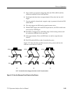
5. After the firmware recognizes the request for service, the FPACK-- line is set
low, which enables the DATAI and CLKI tristate buffers.
6. The data is then clocked out of the switch matrix shift registers.
7. After the data has been clocked out, the FPACK-- line is set high, disabling
the DATAI and CLKI tristate buffers.
8. The rising edge of FPACK-- is also used to reset the request for service flip
flop.
9. The board is now ready for another key press.
There are two diagnostic tools available for the front panel, the key test and the
LED test. These diagnostic tools reside in instrument firmware. They are used
during initial board turn on and when the front panel needs repair. Descriptions
for these diagnostic tools follow.
Key Test. The key test is located in the extended diagnostics menu of the
instrument and consists of text prompting the technician on which key to press.
If the correct key is pressed, its location in the switch matrix and the next switch
to be pressed are displayed. If the incorrect key is pressed, the speaker beeps, and
the same key press is prompted again. Up to four incorrect key presses are
allowed before the firmware continues on to the next key.
LED Test. The LED test is also located in the extended diagnostics menu of the
instrument and uses the knob to light each LED one at a time, in a known
sequence. By rotating the knob, each LED is lit. The test runs until the backspace
key is pressed.
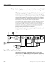
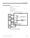
Power Supply (Primary and Secondary)
The Power Supply operates with a line input voltage from 90 VAC to 250 VAC
without range switching. This is done by regulating the rectified AC input
(125 V to 350 V) to 60 VDC.
An inverter drives a transformer having numerous secondaries, including a high
voltage winding (1400 V peak) for the CRT supplies. The secondary voltages are
rectified to provide operating power for the instrument.
The high current secondary output, +5 V, is regulated by feedback to the primary
pulse width modulator. The other secondary outputs track +5 V fairly closely,
except for the high voltage supplies, which have secondary regulation.
The Power Supply circuits are divided into the primary circuits and the
secondary circuits.
Diagnostics and
Testability