Theory of Operation
3-78
2715 Spectrum Analyzer Service Manual
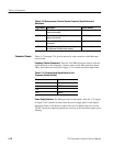
This circuit takes in HCMOS logic levels and produces shaped and risetime
controlled control signal(s) having the characteristics required by the IF gate
circuit. The IF_GATE_EN signal is first passed through CMOS inverter U6
powered from a locally regulated +5 V source to produce output voltage levels
which are well defined, stable, and noise free. The circuit comprising Q5, Q6,
Q8, Q11, and Q12 is a crude operational amplifier with a well defined, intention-
ally low slew rate. Its purpose is to convert the abrupt logic level transitions into
linear ramps having controlled rise and fall times. R27, R33, R37, and R44
provide scaling and offset to this signal to provide the correct drive waveform to
the steering circuit that makes up the IF gate proper.
Video Demodulator
The primary purpose of the video demodulator is to produce TV sync pulses
derived from video modulation on the 110 MHz IF signal. These pulses are used
by other circuitry to control the timing of the IF gate and so forth. It is necessary
that the sync pulses be available whenever the spectrum analyzer is tuned
anywhere within the selected TV channel. A secondary function of this module
is to pass on a slightly amplified sample of the 110 MHz IF signal to the FM
(satellite) TV demodulator located on the sweep board.
Operation of the video demodulator board is described as follows:
Input IF signals near 110 MHz are amplified by about 13 dB in U3, then applied
to a splitter, one output of which relays most of the signal to the satellite TV
demodulator. The signal from the other output is loosely bandpass filtered by L2,
C5, and C8, then sent through a 2nd gain stage (U5) (whose function is primarily
to provide reverse isolation) to a highpass filter with a cut--on frequency of about
104 MHz. Output from this filter is then applied to a downconverter (U4) which
converts the signal to 45.7 MHz (visual carrier) without further frequency
inversion (the 110 MHz IF signal is already frequency inverted from the
spectrum analyzer input). The 45.7 MHz signal then passes through a SAW
(surface acoustic wave) filter which imposes final bandpass limiting and
provides the Nyquist slope for correct detection of vestigial sideband TV signals
by the subsequent detector IC.
Local oscillator for the downconverter is generated by an internal VCO whose
frequency is maintained in part by an AFC loop whose error signal comes from
the video detector IC. This AFC loop is used to keep the mixer output frequency
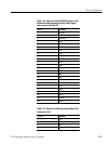
at 45.7 MHz while the input frequency ranges from 108.5 to 114.5 MHz as a
function of the spectrum analyzer’s center frequency setting. The V CO is tuned
by a dual varactor (CR2) which resonates with L5. One part of this varactor
receives a programmed tuning voltage from a DAC (U6) which is set by the
instrument’s firmware according to the frequency difference between the visual
carrier and the instrument’s center frequency setting. The other part receives the
AFC error voltage if AFC is ON; otherwise, it receives a fixed midrange voltage.
Control Signal Conditioner
110MHzto45.7MHz
Downconverter


