Maintenance
2715 Spectrum Analyzer Service Manual
6-17
Assembly Replacement Requiring Flatness Correction
Replacement of any of the following assemblies will require completion of the
Amplitude Flatness Adjustment Procedure on Page 5--52.
H RF Attenuator (A18)
H 1st Converter (A16)
H YIG Oscillator (A19)
H YIG Buffer Amplifier (A17)
H 1845 MHz Lo Pass Filter (FL16)
H 4.5 GHz Lo Pass Filter (FL18)
H Log Amplifier (A7)
H Display Storage (A9) - File Restore (NVRAM)
H RS-232 (A11) or GPIB (A15) Interface - File Restore (NVRAM)
H 2110 MHz Bandpass Filter (FL17)
Removing and Replacing Assemblies and Subassemblies
Most assemblies or subassemblies in this instrument are easily removed and
replaced. The following describes procedures for replacing those assemblies that
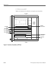
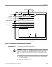
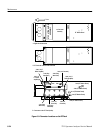
require special attention. Top and bottom views are shown in Figure 6--4 and
Figure 6--5, respectively. These illustrations show the locations of most
assemblies.
The Microprocessor, Display Storage, Digital Options, and Video Demod boards
must be placed on an extender to access test points or adjustments. A second
extender card is added to the main extender for use with the Center Frequency,
Log, and RF Options boards.
Turn the power off before removing an assembly.
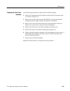
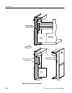
Use the following procedure to remove the instrument from the cabinet.
1. Remove the power cord.
2. Set the instrument on its face with the front cover installed.
3. Remove the rear cover (two T15 Torx-drive screws), two (front) top and
bottom feet (four T15 screws), three pan head screws from the bottom rear ,
and two pan head screws from the top rear of the instrument.
Removing the Instrument
from its Cabinet


