


Theory of Operation
2715 Spectrum Analyzer Service Manual
3-15
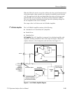
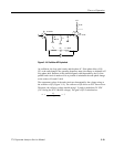
When the FM coil is used to sweep the oscillator, the relay on the Interface board
closes and couples a large capacitor (two capacitors in parallel) across the main
coil. The capacitors lower the noise bandwidth of the main coil driving circuit
while the FM coil is in operation. The heater provides temperature stability.
The rest of the circuitry on the Interface board provides operating voltages for
the two amplifiers in the 1st LO assembly.
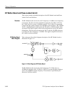
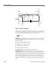
The output of the 1st LO drives the 1st LO Buffer Amplifier.
The 1st LO Buffer Amplifier consists of the following:
H Automatic Level Controlled (ALC) Amplifier
H Strobe Driver
H Sampling Gate
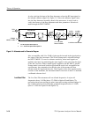
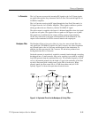
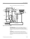
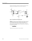
ALC Amplifier. The ALC Amplifier is composed of a wide band amplifier with
impedance matching transmission lines at the input and output, a directional
coupler, a detector, a level comparator, and active bias. S ee Figure 3--7.
1st LO In
1st LO Out
Detector
-- V R E F
Beat Note to Phase
Lock CFC Module
Sampling
Gate
STROBE from Center
Frequency Control Board
(25.7325 MHz to 26.05 MHz)
Reserved for Options
ALC Amplifier
Strobe Driver
Terminator
replaced by
semi-rigid cable
when Option 15
is installed
Figure 3- 7: 1st LO Buffer Amplifier Diagram
1
st
LO Buffer Amplifier