Operating Information
2-4
2715 Spectrum Analyzer Service Manual
Replacing the Fuse
Replace the line fuse with a 2 A Slow Blow fuse.
Selected Components
Some components are specifically selected to meet Tektronix specifications.
These components are shown in the parts list.
Selected value components are identified in the parts list as a SEL value. The
component description lists either the nominal value or a range of values.
Assembly and Circuit Numbering
Each assembly and subassembly is assigned an assembly number. Generally,
each component is assigned a circuit number according to its geographic location
within an assembly. The Replaceable Electrical Parts list prefixes these circuit
numbers with the corresponding assembly and subassembly numbers.
Example: R260 on assembly A14 becomes A14R260.
Example:U140 on subassembly A1 of assembly A19 is found in the
electrical parts list as A19A1U140.
Accessories
The Replaceable Mechanical Parts section contains part numbers, descriptions,
and ordering information for all standard and optional accessories offered for this
Spectrum Analyzer.
Refer to Appendix F: Accessories & Options in the 2715 Spectrum Analyzer
User Manual for listings of standard and optional accessories.
Refer to Section 7: Options in this manual for information on accessories
associated with options.
The Accessories at the end of the Replaceable Mechanical Parts in this manual
contains information on all standard accessories currently available with this
Spectrum Analyzer.
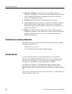
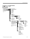
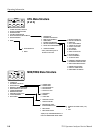
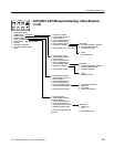
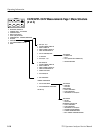
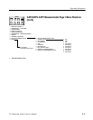
Menus
There are eight menus of selections that are used to invoke most of the setups,
operational modes, and applications.


