


Maintenance
6-6
2715 Spectrum Analyzer Service Manual
Performance Checks and Recalibration. The instrument performance should be
checked after each 2000 hours of operation or every 12 months, if the instrument
is used intermittently, to ensure maximum performance and assist in locating
defects that may not be apparent during regular operation. Instructions for
conducting a performance check are provided in Section 4: Performance
Verification of this manual.
Stored Data in Nonvolatile Memory. Data stored in nonvolatile memory will be lost
if backup battery power to the memory is interrupted, such as when changing the
battery.
Troubleshooting
The Spectrum Analyzer contains firmware that will troubleshoot the frequency
control system. After a defective assembly or component is located, refer to
Removing and Replacing Assemblies and Subassemblies on Page 6--17 for
removal and replacement instructions.
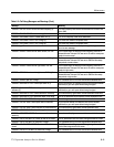
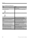
The following aids are provided to assist in troubleshooting:
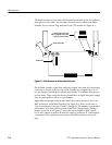
Diagrams. Functional block and circuit diagrams, on foldout pages in the
Diagrams section, contain significant waveforms, voltages, and logic data
information. Conditions for getting the data are provided on the diagram or
adjacent to it. Refer to the Replaceable Electrical Parts list for a description of
all assemblies and components.
Replaceable Electrical Parts. This list indicates changes to components with serial
numbers showing the first serial number when usage of the part occurred and the
last serial number when usage of the part stopped. Absence of serial numbers
indicates the parts were in use since the first instrument shipped. When a major
modification is made to an assembly or board and it is no longer compatible with
earlier instruments, a new part number is assigned and a separate schematic with
associated illustrations is added. All diagrams indicate the new part number and
the instrument serial number break. If the assembly is compatible with earlier
instruments and the change is significant enough to require a separate schematic,
this will also be identified.
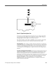
Circuit Board Illustrations and Component Locator Charts. Electrical components,
connectors, and test points are identified on circuit board illustrations that are
located on the inside fold of the corresponding circuit diagram or the back of the
preceding diagram. A grid on the circuit board illustration and the circuit
schematic, plus a look up table, provide the means to quickly locate components
on either the diagram or the circuit board.
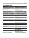
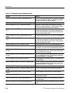
Troubleshooting Aids