


Maintenance
2715 Spectrum Analyzer Service Manual
6-7
In most cases, circuit numbers are assigned according to the physical location of
the component on the board or assembly. The first digit designates the row of a
grid and the second a column.
General Troubleshooting Techniques. Before using test equipment to measure
across static sensitive components or assemblies, be certain that voltages and
currents supplied by the test equipment do not exceed the limits of the compo-
nents to be tested.
Try to isolate the problem to a component through signal analysis. Determine
that circuit voltages will not damage the replacement.
Semiconductor Checks. Semiconductor failures account for the majority of
electronic equipment failures. All semiconductors are soldered to the boards to
reduce pin contact problems. Follow these guidelines when substituting any of
these semiconductors.
H Always turn the power off before removing an assembly or circuit board.
H Use a hot air repair terminal to remove surface mounted components, and a
15 W or less soldering iron to remove components with leads.
H Use only good components for substitution. Be sure the new component is
inserted into the board properly before soldering. Refer to the manufacturer’s
data sheet for integrated circuit and transistor lead configuration.
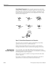
Diode Checks. Most diodes can be checked in the circuit by taking measurements
across the diode and comparing these with voltages listed on the diagram.
Forward to back resistance ratios can usually be taken by referring to the
schematic and pulling appropriate transistors and pin connectors to remove low
resistance loops around the diode.
NOTE. Do not use an ohmmeter scale with a high external current to check diode
junctions. Do not check the forward to back resistance ratios of mixer diodes.
Diagnostic Firmware. The firmware in the Spectrum Analyzer provides diagnostic
routines that can be used to troubleshoot the Frequency Control system.