Maintenance
2715 Spectrum Analyzer Service Manual
6-27
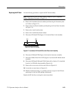
Use the following procedure to replace the 1st LO B uffer Amplifier:
NOTE. Replacement of this assembly requires completion of the. Amplitude
Flatness Adjustment Procedure on Page 5--52.
1. Remove the instrument from its cabinet (see Removing the Instrument from
its Cabinet on Page 6--17).
2. Remove the RF Deck from the Spectrum Analyzer (see Replacing the RF
Deck on Page 6--23).
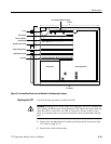
3. Disconnect P100 and P380 from the 1st LO Buffer Amplifier assembly.
4. Remove the Step Attenuator (see the previous step Replacing the Step
Attenuator).
5. Remove two 1/4I nuts and a screw holding the 1st LO Buffer Amplifier in
place. The screw is located in the corner of the 1st Converter assembly.
6. Remove the 1st LO Buffer Amplifier assembly from the RF deck.
Replace the assembly by reversing the removal procedure.
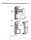
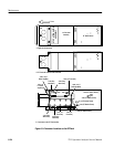
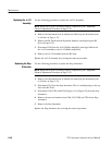
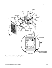
Refer to Figure 6--10 for the following removal procedure for the fan:
1. Remove the instrument from its cabinet (see Removing the Instrument from
its Cabinet on Page 6--17).
2. Position the instrument with the rear of the instrument facing the installer.
3. Remove the fan shroud by removing the two 4-40 nuts.
4. Remove the fan connector.
5. Remove the fan and mounting springs by removing the four 4-40 Pozidriv
screws. The fan becomes free with the mounting springs still attached.
6. Remove the two 6-32 mounting screws (and nuts) to separate the mounting
springs from the fan.
Replacing the 1
st
LO
Buffer Amplifier
Replacing the Fan
Assembly


