


Performance Verification
2715 Spectrum Analyzer Service Manual
4-3
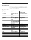
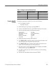
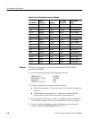
Table 4- 1: Equipment Required (Cont.)
Test Equipment RecommendedCharacteristic
BNC T Adapter Tektronix Part No. 103-0030-00
Adapter, N Male to BNC Female 50 Ω Tektronix Part No. 103-0045-00
Adapter, Female-to-Female F 75 Ω Tektronix Part No. 103-0301-00
Adapter, 75 Ω Female-to-Female F 75 Ω Tektronix Part No. 103-0310-00
BNC Female to Female A dapter Tekt roni x Part No. 103-0028-00
Min loss attenuator (2) 50 -- 75 Ω Tektronix Part N o. 011-0057-01
Two 50 Ω Coaxial Cables Tektronix P art No. 012-0057-01
FM Antenna Any commercially available FM antenna
Two Function Generators 0.002 Hz to 20 MHz 20 mV to 20 V Tektronix FG 5010 with TM 5000 Series
Power module
Mainframe For TM 500 and TM 5000 series Plug ins Tektronix TM5006A
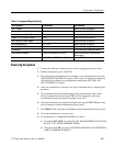
Power-Up Procedure
1. Connect the Spectrum Analyzer power cord to an appropriate power source.
2. Push the front panel power switch ON.
3. The instrument will initialize itself according to the configuration stored in the
USER DEFINED POWER-UP register. If this register is empty, the instrument
will initialize according to the configuration stored in the FACTORY DE-
FAULT POWER-UP register.
4. Allow the instrument to warm up for at least 30 minutes before continuing this
procedure.
5. The instrument must be normalized before any measurements can be made.
Invoke normalizations by pressing UTIL 3 0. The instrument will begin
normalizations and print progress messages on the CRT.
6. After the instrument has completed normalization, press UTIL550and verify
that all frequency related normalizations have passed.
7. Press BKSP 2 and verify that all amplitude related normalizations have passed.
8. Press any menu button to exit the menu.
9. Set instrument to CALIBRATION MODE as follows:
a. Press the CATV/APPL key then, 8 (CATV MEASUREMENT SETUP) and
0 (EXIT CATV MEASUREMENT MODE).
b. Next press the UTIL key then, 5 (INSTR DIAGNOSTIC/ADJUSTMENTS)
and 8 (CALIBRATION MODE).