


Theory of Operation
3-4
2715 Spectrum Analyzer Service Manual
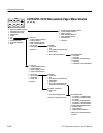
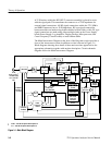
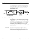
The RF Mother board assembly contains a 2 GHz 2nd LO, a 2nd Converter,
several gain stages, a 5 MHz resolution bandwidth filter, and a 3rd Converter.
The 2nd Converter down converts the 2110 MHz 1st IF to 110 MHz. The 3rd
Converter down converts the 110 MHz 2nd IF to a 10 MHz 3rd IF. This signal is
routed to the Variable Resolution module.
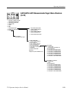
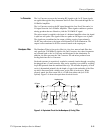
The Variable Resolution contains several selectable gain stages prior to the filters
and a compensation amplifier. One of the nine filters is selected. Each filter has
an attenuator pad associated with it to compensate for losses in the filter. The
system selects the appropriate amplification factor as each filter is selected.
The 10 MHz IF signal is processed through one of several Bandpass filters,
amplified once more, and then routed to the Log Amplifier board.
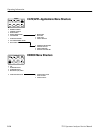
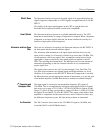
The Log Amplifier performs the logarithmic conversion, linear detection and
logarithmic detection of the incoming signal, and amplitude calibration. The log
display has scale factors of 10 dB/div, 5 dB /div, and 1 dB/div. The module also
contains an FM detector, an audio amplifier, an amplitude limited output for the
period counter, and an out-of-band signal clamp.
The detector produces a voltage that corresponds to the input signal strength in
decibels. The detector output is then vertically scaled and sent to the Display
Storage and Sweep boards.
The control processor uses three 8 bit shift registers to control the Log Amplifier.
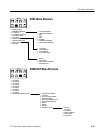
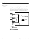
The Display Storage board contains the circuitry for putting text and waveforms
onto the CRT display.
This board contains the following programmable functions:
H Waveform Storage — four 512 point waveforms
H Dot Markers — up to two intensified markers
H Text S torage — four 32 character by 16 lines of text
H Accumulator data — direct access to the output of the A to D converter
H Nonvolatile memory — 32 Kbytes total; 2 Kbytes used for waveforms;
2 Kbytes used for text; the rest is available for general use
When enabling the analog display, waveforms A, B, C, and D are turned on, but
not displayed. This results in a chopped blanking effect between the readout and
the analog display. The scanning alternates between the readout and the analog
display.
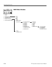
RF Mother Board
Assembly
Variable Resolution
Module
Log Amplifier
Display Storage