Theory of Operation
2715 Spectrum Analyzer Service Manual
3-63
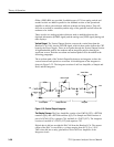
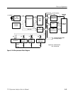
The Clock Generator chip (U360) is an NEC PD71011. The purpose of this IC
is to generate the clock for the Microprocessor board and synchronize the
insertion of wait states into the CPU.
The Clock Generator part of the IC uses a 14.7456 MHz crystal (parallel
resonant) to generate the 7.3728 MHz CPU clock (14.7456 MHz ÷ 2). In
addition to the CPU clock output, there is an oscillator clock output that is
divided by six (÷6) using three flip flops (U240). The output of this ÷6
(2.4576 MHz) is used to drive the Display Storage and GPIB or RS--232C board
state machines.
The wait state synchronization part of U360 is not used but is replaced by a flip
flop (U260A). Timing errors between a wait state generator on the GPIB or
RS--232 board and the CPU are eliminated by synchronizing the RDY signal
(pin 25 of U250). Since the CPU allows the RDY line to go low asynchronously,
relative to the CLK88 signal, U260A is cleared as soon as the BWAIT-- signal
goes low. After the BWAIT-- signal goes high, the RDY signal is synchronized,
through U260A, using the CLK88 signal. This prevents any timing problems
regarding the generation of wait states.
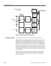
The Interrupt Controller (U340) is based on the NEC PD71059 (Intel 82C59).
The purpose of the Interrupt Controller is to synchronize and set up priority for
up to eight system interrupts. A high level on any of the IR0 through IR7 inputs
of the Interrupt Controller causes the INT output (pin 17 of U340) to become
high. After the CPU recognizes the interrupt on the INTR input (pin 20 of
U250), it pulls the INTA output (pin 27 of U250) low, telling the Interrupt
Controller that the CPU is ready to accept the interrupt data. The Interrupt
Controller then disables the data buffer outputs (U460), through XDEN-- on
pin 20 of U530, and presents the interrupt data on the data bus during the second
low pulse on the INTA signal from the CPU.
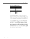
The interrupt inputs to the Interrupt Controller are configured as shown in
Table 3 --15. The priority is determined by both the settings of the internal
registers of the Interrupt Controller and the interrupt input number (IR0 has
highest priority by default).
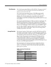
Table 3- 15: Interrupt Controller Input
Connections
Interrupt Number System Connection
IR0 Programmable Interval Timer 0
IR1 I/O Subsystem Interrupt
IR2 End of Sweep Interrupt
IR3 Frequency Counter Done Interrupt
IR4 Digital Options Board
Clock Generator
Interrupt Controller


