Maintenance
6-32
2715 Spectrum Analyzer Service Manual
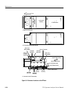
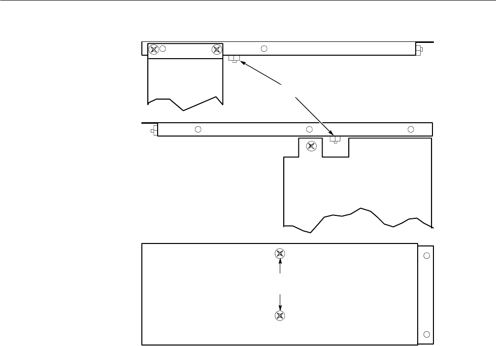
Remove Two Nuts
Top of right side chassis
Power Supply Board
Bottom of right side chassis
Outside view of the left
side chassis
Rear plug in circuit board guide
plate-to-left side chassis screws
Variable
Resolution
Module
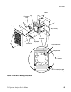
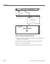
Figure 6- 12: Removing Power Supply Attaching Nuts
12. Remove the two nuts that fasten the front plug-in circuit board guide to the
rear plug in circuit board guide.
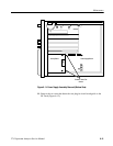
13. Undo the cables threaded through the rear plug-in circuit board guide.
14. Remove the Power Supply assembly.
Replace the Power Supply assembly by reversing the removal procedure.


