


Theory of Operation
3-84
2715 Spectrum Analyzer Service Manual
The FPREQEN-- signal is used to enable the front panel request output buffer. If
FPREQEN-- is in the inactive state, the front panel service request line to the
microprocessor will always be active (always requesting service).
The CLKIEN-- signal is reserved for future use.
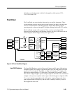
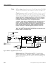
The Switch Matrix consists of 59 normally open single pole, single throw
switches. These switches are configured in a 6 × 11 matrix (possibility of 66
switches total). By using this matrix, it is possible to determine the location of a
closed switch by looking at the rows and columns of the matrix.
Each column in the matrix is held low by a 100 kΩ resistor to ground, while the
rows are connected to the +5 V supply through a 22.1 kΩ resistor and to the base
of an open collector transistor. When all the switches are open, the transistor is in
the off state, thus the row line is low (ground). When a switch is closed, the base
of the transistor is pulled down to approximately 4.3 V and the transistor turns
on, thus pulling the row line to the +5 V supply. At the same time, the column
line is pulled high due to the resistor divider on the base of the transistor.
The row and column lines are fed to inputs of three parallel to serial shift
registers. In addition to the shift registers, the row lines are wired to form a
phantom OR gate whose output triggers a debounce circuit.
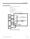
Switch Matrix Debounce Circuit. The debounce circuitry for the switch matrix
consists of three retriggerable single shots. Two of these single shots are used to
establish the minimum time between key presses. The third single shot is used to
debounce the switch being pressed.
The two single shots used to establish the minimum time between key presses
operate as follows:
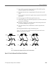
The row lines of the switch matrix are wired to form a phantom OR gate whose
output drives the trigger inputs of both single shots. Each single shot triggers on
the opposite edge of the other. The rising edge triggered single shot is called the
Press One Shot (POS), while the falling edge triggered single shot is called the
Release One Shot (ROS).
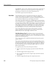
For a typical key press, the one shots will operate as follows:
1. The key is pressed and a rising edge is presented to both the POS and the
ROS.
2. The P OS is triggered and its output goes active.
3. Due to the bouncing of the switch, a negative edge is presented to both the
POS and ROS.
4. The R OS is triggered by this edge and its output becomes active.
Switch Matrix