Maintenance
2715 Spectrum Analyzer Service Manual
6-9
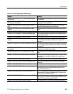
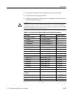
Table 6- 2: Cal Debug Messages and Meanings
Message Meaning
“ERROR in REF GAIN STEP OFF: Cannot set external signal
near full screen”
The signal could not be placed at or above full screen by reducing
RF attenuation.
“ERROR in REF GAIN STEP OFF: Cannot set signal to below
0.75 division from full screen”
The signal could not be placed exactly 0.75 division full screen by
using only the VR fine gain DAC.
“ERROR in REF GAIN STEP ON: External signal at incorrect
level”
The signal did not drop at least 70 storage locations when the
operator reduced the signal by 10 dB (lin mode).
“ERROR in REF GAIN STEP ON: Cannot measure lin mode
sensitivity”
The calculations for lin mode sensitivity were outside reasonable
limits.
“ERROR in REF GAIN STEP ON: Result out of range” The calculated result for this test was outside reasonable limits.
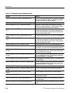
”ERROR in REF FREQUENCY: Cannot count reference signal” The user applied reference signal could not be counted using the
center measure function.
“ERROR in REF FREQUENCY: Result out of range” The calculated result for this test was outside reasonable limits.
“ERROR in REF AMPLITUDE: Cannot span down on external
signal (1)”
The externally applied signal could not be set to zero span, 5 MHz
filter. Probably due to frequency instability in the signal or the
instrument.
“ERROR in REF AMPLITUDE: Cannot set calibrator to full screen” The user applied reference signal could not be set a hal f a division
from full screen using VR gain steps, RF attenuators, and the VR
fine gain DAC.
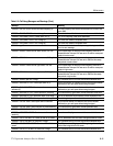
“ERROR in REF AMPLITUDE: No amplitude change when 10 dB
step changes”
The 10 dB reference step was removed to calculate the l in mode
sensitivity. The amplitude did not change.
“ERROR in REF AMPLITUDE: Lin mode sensitivity of range” The calculations for lin mode sensitivity were outside reasonable
limits.
“ERROR in REF AMPLITUDE: Cannot span down on calibrator” The internal calibrator signal could not be set to zero span, 5 MHz
filter. Probably due to frequency instability in the signal or the
instrument.
“ERROR in REF AMPLITUDE: Result out of range” The calculated result for this t est was outside reasonable limits.
“ERROR in VCO UPPER SENS: Cannot count phase lock VCO” The LF VCO could not be counted at some poi nt on the upper
VCO DAC.
“ERROR in VCO UPPER SENS: Result out of range” The calculated result for this test was outside reasonable limits.
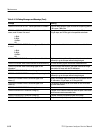
“ERROR in VCO UPPER SENS: Cannot calculate polynomial” The coefficients for the curve fitting algorithm could not be
calculated. One of the 20 sample points taken along the VCO
curve were probably in error.
“ERROR in VCO LOWER SENS: Cannot count phase VCO (1)” The LF VCO could not be counted when the upper VCO lock DAC
was set for a VCO frequency of approximately 13.4 MHz and the
lower VCO DAC was at center (2047).
“ERROR in VCO LOWER SENS: Cannot count phase VCO (2)” The LF VCO could not be counted when the upper VCO lock DAC
was set for a VCO frequency of approximately 13.4 MHz and the
lower VCO DAC was at its upper limit (4095).
“ERROR in VCO LOWER SENS: Result out of range” The calculated result for this test was outside reasonable limits.


