Theory of Operation
2715 Spectrum Analyzer Service Manual
3-27
This allows for 1st LO drift or user changes to the center frequency setting
without having to drop and reacquire lock for every change.
If Q652 is turned on by the signal UNLKIND (signifying that the inner loop is
unlocked), both INCR MAIN and DCR MAIN are turned on simultaneously.
This is a unique condition that the microprocessor interprets as a hardware
failure in the VCO module.
Summary of Outer Loop Lock Acquisition. When the instrument is placed into a
situation calling for phase lock operation, several things are done by the
firmware to arrange for a lock at the correct frequency.
The N number (that is, the harmonic order of the strobe to which the 1st LO will
lock) is calculated, and the strobe and corresponding VCO frequencies needed
are calculated. The sweep is disconnected, the FM coil DAC is set to mid range
(FM coil current to nominal zero), and the main coil DAC is set to the value that
will place the 1st LO as close as possible to the desired 1st LO frequency (it can
be several hundred kHz off because of the coarseness of the main coil DAC
steps). Now the VCO is tuned by trial and error so that the strobe line, at a
frequency of N X F
strobe, is approximately 100 kHz above the actual 1st LO
frequency (that is, the measured beat frequency is 100 kHz on the correct side of
zero beat). Then, lock is invoked by setting PLLCON high. Due to the intention-
al offset provided by R709, the 1st LO drifts rapidly into lock. After a suitable
delay, acquisition of lock is verified by checking the states of both lock limit
comparators and by checking that the beat frequency is zero.
At this point the loop is locked, but in the wrong spot. Now the microprocessor
proceeds to tune the VCO (and consequently, the strobe and 1st LO) to the
correct frequency by repeatedly tuning and counting the VCO. The sweep is then
switched into the VCO tuning voltage, and the instrument is now scanning the
desired spectrum range.
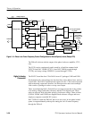
Wide Span Operation (5.1 MHz/div and Higher Spans). TheMaincoilisdrivenbya
fixed bias summed with DAC U950A output and a sweep signal (routed through
U830A).
The FM coil is driven with VCFC FM arising from DAC U850A only (routed
through U757A). Current is routed through Q910 and Q911 to the FM coil. See
Figure 3--12.
Signal Path and Switching
Summary


