Theory of Operation
2715 Spectrum Analyzer Service Manual
3-83
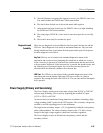
All of the control information is shifted in through four shift registers U211,
U312, U610, and U520.
Front Panel
The Front Panel acts as an interface between the user and the instrument. These
circuits translate operator actions on front panel controls into data for the micropro-
cessor to read and execute. The Microprocessor outputs data showing current
operating modes to the user through LEDs (light emitting diodes) and CRT readout.
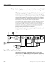
The Front Panel consists of five sections. These sections are the Input Shift
Registers, the Switch Matrix, the Debounce circuitry, the Gray Code Knob, and the
Service Request/Acknowledge circuitry. See Figure 3--26.
Switch
Debounce
Input Shift
Registers
6/
FPREQEN --
Switch Matrix
11x 6
(59 Total)
Switch
Debounce
And
Wire
Or
Service
Request and
Acknowledge
Circuit
Gray Code
Knob
Output Shift
Registers
Vcc
17 LEDs
Total
Vcc
FPLATCH
DATAO
CLKO
FPREQ--
TLVL
FPACK--
2/
DATAI
CLKI
CRTINTS--
VLVL
2/
Front Panel
Potentiometers
6/
11/
Figure 3- 26: Front Panel Block Diagram
The Input Shift Registers consist of three serial input, parallel output shift registers
cascaded together. The outputs of the shift registers drive the front panel LEDs and
provide two control signals. The LEDs are connected from the +5 V supply to the
shift register output through a 274 Ω resistor. The nominal LED current is 10 mA.
This current is high enough to provide adequate light for the LED to be seen in direct
sunlight. A low (zero) is required on the output of the shift register to light the LED.
Two control signals are provided on the shift register outputs. They are the front
panel request enable (F PREQEN--) and the clock in enable (CLKIEN--). Both of
these signals are active low.
Input Shift Registers


