


Theory of Operation
3-2
2715 Spectrum Analyzer Service Manual
A25Ω resistor within the RF INPUT connector assembly is placed in series
with the signal path. This transforms the connector to a 75 Ω impedance for
external signal connections. All RF signal connections within the 2715 (SMA
and SMB connectors) have a 50 Ω impedance. RF type signal connections
between modules are made using double shielded coaxial cables, while DC type
signal connections are made using either multipin jacks on the Power Supply
board (Power Supply, Log Amplifier, Display Storage, Microprocessor, and
Center Frequency Control boards) or small ribbon cables.
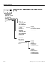
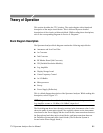
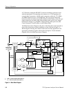
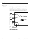
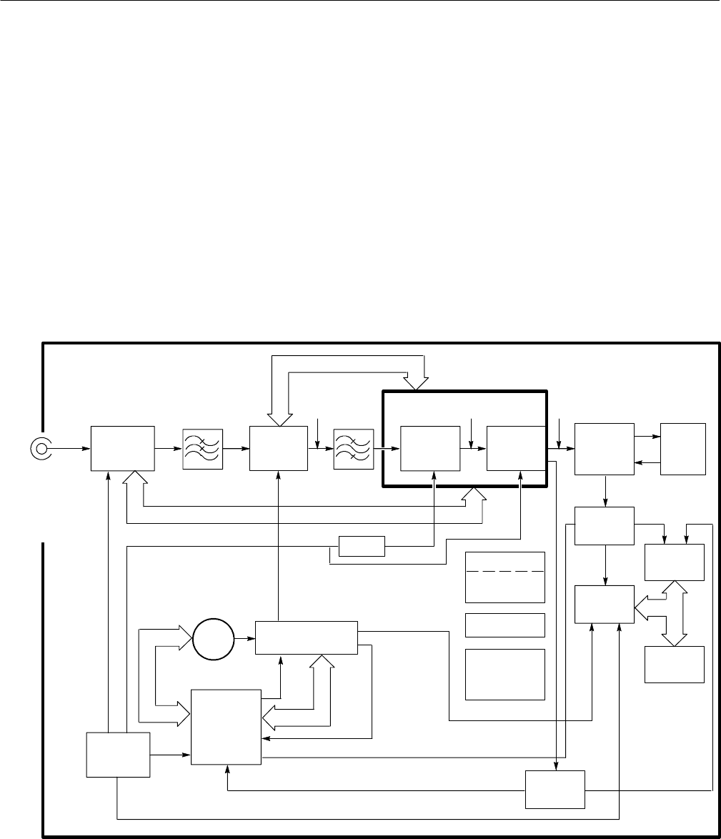
The Main Interconnect Diagram at the front of the Diagrams section provides a
chart of the interconnect system in addition to what is shown in Figure 3--1.
Block diagrams showing more detail of these main sections appear before the
appropriate schematics together with another description. Circuit schematic
diagrams follow the Main Interconnect Diagram.
6/
RF IN
9kHz-1.8GHz
1
+70 dBmV MAX,
75 Ω 100 VDC
Max
2110 MHz
1st
Converter
Attenuator
2.11 − 3.91 GHz
2
+11 dBm MIN
+14.5 dBm MAX
From 1st LO Buffer
2nd
Converter
3rd
Converter
110 MHz
Variable
Resolution
Module
10 MHz
RF
Options
Reference
Oscillator
3/
RF Mother
Board
10/
10 MHz
--10 dBm
Log
Amplifier
Display
Storage
Micro-
processor
Digital
Port
1st LO
Center
Frequency
Control
Power Supply
with Deflection
System
Front Panel
Rear Panel
Controls &
Connector
2nd LO
2GHz100 GHz
COUNT10/
SWPSLOPE
Log
Amplifier
50/
Calibrator
(100 MHz/
--22 dBm)
1
9 KHz – 2.15 GHz for Option 50 and Option 75
2
2.11 – 4.26 GHz for Option 50 and Option 75
Figure 3- 1: Main Block Diagram