


Theory of Operation
2715 Spectrum Analyzer Service Manual
3-41
H Provides for the ability to place up to two markers on a displayed waveform
H Implement and display a B,C--Save A waveform
H Display readout information on the screen
H Provide up to 28 Kbytes of nonvolatile storage area
H Provide two different waveform acquisition modes: Max Peak and Min/Max
H Provide a Max Hold function
The following sections show the bit maps for each of the control registers on the
Display Storage board.
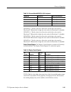
Mode Control Register 1. Mode Control Register 1 is located in I/O space, at
location 0x0FA00. Mode Control Register 1 is a read/write register. Table 3--2
describes the Mode Control Register.
Table 3- 2: Mode Control Register 1
Bit
Number
Mnemonic
Activity
Level
Description
7 DSON_L Low Display Storage On
6 DISP--A_L Low Enables B,C--Save A Display
5 MAXHLD_L Low Enabl es max hold function
4 PEAKDIS_L Low Enables max peak function
3 HLF/FLL_L High Selects location of B,C--Save A display
2 ACQ_ON High Enables the acquisition system
1 RDZEN High Not used
0 DS_PROTECT High Not used
DSON_L. Enables the Display Storage board to display the digitized waveforms
when low. When this signal is high, the analog trace is drawn on the CRT.
DISP--A_L. Invokes the B,C--Save A display on the CRT when low.
MAXHLD_L. Invokes the Max Hold algorithm for A and B waveforms when
low. In this mode a given bin will only be updated when the new vertical data is
greater than the stored vertical data.
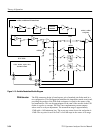
Control System Interface