Theory of Operation
2715 Spectrum Analyzer Service Manual
3-19
R
t
82.5 Ω
C
m
L
m
C
p
L
t
C
t
Q1
Q2
+5 V
221 Ω
r
e1
≈ 8.3Ω
r
s
=50Ω
r
e2
=5.7Ω
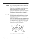
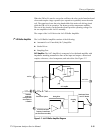
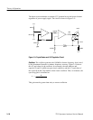
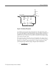
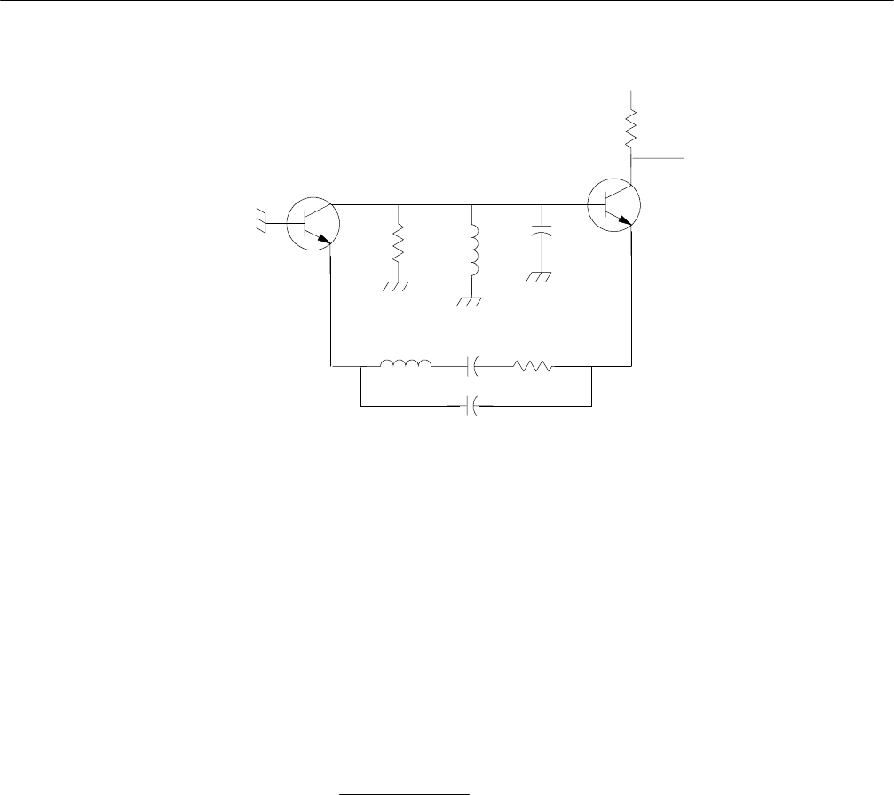
Figure 3- 1 0: Oscillator AC Equivalent
At oscillation, the loop gain is unity and the phase 0°. If the phase delay of Q1,
Q2, or the tank changes, the operating frequency must also change to maintain a 0°
loop phase shift. Because of this phase/frequency shift dependency, the Q of the
parallel tank circuit is made as low as possible to minimize the tank phase change
as the values of Lt and Ct drift.
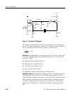
The component values of the tank circuit are determined by the voltage swing at
the collector of Q2 (Figure 3--11). The collector of Q2 drives an ECL line receiver.
Therefore, the collector voltage should swing 1 V peak to peak about 3.8 VDC
(3.8 V being the ECL Vbb bias voltage). The gain of Q2 is calculated as:
A =
R
t
(r
e1
+ r
e2
+ r
s
)
= 3


