


Theory of Operation
2715 Spectrum Analyzer Service Manual
3-37
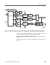
The board provides the resolution bandwidths used to fill in between filter values
installed within the Variable Resolution module. The bandwidth range is 1 MHz
to 1 kHz in decade steps, and 300 Hz. Each filter path consists of a switchable
amplifier and bandpass filter combination.
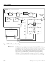
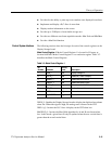
The control of the RF Options by the microprocessor is through one 8 bit shift
register. Data is shifted serially in one 8 bit word.
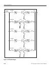
The variable bandwidth section consists of a switching tree to select one of five
filters. Available bandwidth filters, in addition to those already in place in the
Variable Resolution module, are 1 MHz, 100 kHz, 10 kHz, 1 kHz, and 300 Hz.
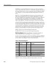
A resistor is installed between either pin 12 (d6) or pin 13 (d5) of shift register
U390 and the base of Q396 to complete a path for an identification bit for the
Microprocessor. This allows the Microprocessor to determine that the 300 Hz
filter is installed on the RF Options board.
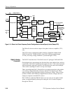
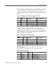
The gain stage used is a transformer feedback stage that provides approximately
11.5 dB of gain. In the case of the 100 kHz and 300 Hz filters, two gain stages
are used. The impedance match at one port of the Gain Stage is highly sensitive
to a proper termination being presented to the other port.
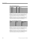
The routing switches are used to route RF signals to the selected bandwidth
filter. They are composed of a transistor in heavy saturation that has relatively
large charge storage characteristics. The topology used is a shunt series
configuration. These switches are used on both the input and output of each
filter. That is, the filters are switched in and out at both the input and the output
so that when a filter is not being used it is effectively out of the circuit.
Each bandwidth filter is composed of a double tuned circuit (a two pole
Butterworth filter section), an amplifier to provide gain correction and isolation,
and another double tuned circuit. The intermodulation performance of the
amplifier is less critical because the amplifier is placed after the filter. The noise
power generated by the stage is reduced by placing a filter of equal bandwidth
after the gain stage.
The identification bit can provide useful information on the proper configuration
of the instrument.
Control System Interface
Bandwidth Control
Identification Bit
Gain Stage
Routing Swit ches
Diagnostics