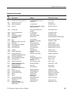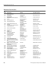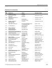
Options
7-2
2715 Spectrum Analyzer Service Manual
This is a no cost option that adds the IEEE Standard 488 General Purpose
Interface Bus (GPIB). The pertinent circuits are located on the Digital Option
board. The GPIB port consists of three compartments. They are the general
purpose interface bus controller, an octal bus transceiver, and an eight channel
transceiver. In addition, there is circuitry included to drive two LEDs to display
the status of the Not Ready For Data (NRFD) and Not Data Accepted (NDAC)
handshake lines.
The general purpose interface bus controller, octal bus transceiver, and eight
channel transceiver meet the IEEE-488 1975/78 standards along with the
IEEE-488A1980 supplement.
For programming, see the 2714 & 2715 Programmer Manual.
The rear panel connection provides full GPIB printer compatibility.
If this option is specified, Option 08 is not available.
This option adds the 2707 External Tracking Generator (Option 01). In addition,
Option 15 (1st LO output) is included to provide the drive signal for the 2707.
This option comprises the Tektronix 2704 DC Inverter and 2705 Battery Pack.
The Inverter and Battery Pack are designed to allow operation of the Spectrum
Analyzer in locations where AC power is not available.
The Inverter and Battery Pack combination is capable of operating the Spectrum
Analyzer for a minimum of one hour. Moreover, the Inverter contains a charger
and an 18 VDC output to power external devices such as Low Noise Block
(LNB) Down Converters used in satellite down link applications. The Inverter
also includes an additional 12 V input to allow use of external batteries without
power interruption to the Spectrum Analyzer. The Inverter and Battery Pack
form a matching unit and attach together to the Spectrum Analyzer. At least one
Battery Pack is needed with each inverter for normal operation and to add
stability when mounted to the Spectrum Analyzer.
Refer to the 2074 Inverter and 2705 Battery Pack Instruction Manual for
specifications, installation instructions and other pertinent information.
This option adds the RS-232 Interface port, a no cost option. The pertinent
circuits are located on the RS-232 board. If this option is specified, Option 03 is
not available.
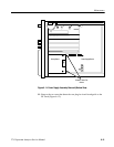
This option provides an interface for the 1405 TV Sideband Analyzer and the
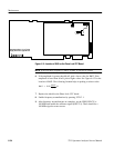
Option 05 External Tracking Generator. The 1st LO is routed from J300 on the
1st LO Buffer Amplifier assembly to J101 at the rear panel and terminated in
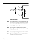
50 Ω. See Figure 7--1.
Option 03
Option 05
Option 07
Option 08
Option 15


