Adjustment Procedures
5-36
2715 Spectrum Analyzer Service Manual
Use the following procedure to perform the Service Normalization.
H Test equipment required:
Signal Generator
Power Meter
10 dB and 1 dB S tep Attenuator Assembly
Two 6 dB Attenuators
Min Loss Pad
GAIN STEP REFERENCE
Use the following procedure to normalize the gain step reference:
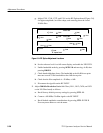
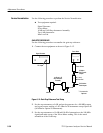
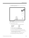
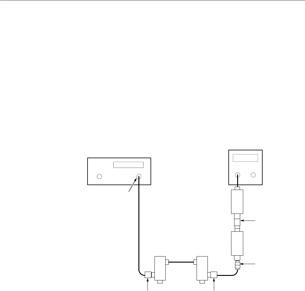
1. Connect the test equipment as shown in Figure 5 --12.
Signal Generator
10 dB and 1 dB
Step Attenuator
Assembly
6dBPad 6dBPad
RF Output
N Male to
BNC Female
Adapter
BNC Male to
Male Adapter
Power Sensor
Power Meter
50 -- 75 Ω
Min loss Pad
*
*
Do not use for
Option 50
Figure 5- 12: Gain Step Reference Test Setup
2. Set the step attenuators to 0 dB, and set the generator for a 100 MHz output
and a power meter reading of --0.2 dBm for all instruments except Option 50
(0.0 dBm for Option 50 instruments).
3. Set the step attenuators to 10 dB (add 10 dB of attenuation to the 100 MHz
signal) and make a note of the Power Meter reading. This is the actual
attenuation of the 10 dB step.
Service Normalization


