o
o
o
I
.|
r
o
o
a
a
o
I
o
o
t
a
o
O
o
o
o
I
a
o
o
o
t
o
a
a
I
I
I
o
o
o
o
o
I
o
a
a
a
o
tv
49441494AP
Servtce
Vot.
i
Section 4
Section 5
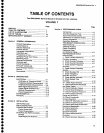
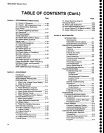
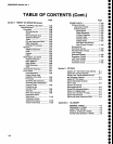
TABLE
OF
CONTENTS
(Gonr.)
page
PERFORMANCE
CHECK
(Conr.)
24.
Check LO
Emission
.....4-29
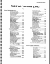
25.
Check 1
dB
Compression
point
.......4-29
26.
Check External
Reference
Input
Power
.... 4-31
27.
Check
Triggering
Operation
and
Sensitivity
..............
..... 4-31
28.
Check
External
Sweep
Operation
...............
4-92
29.
Check
VERT
OUTPUT
Signat
..........
4-34
30.
Check
HORTZ
OUTPUT
Signaf
Level
....4-94
oPTloN
TNSTRUMENTS
.......................
4_34
31.
Check
Option
07
Calibrator
Output
...............
4-94
32.
Check
Option
07
Frequency
Response
......... 4-95
33.
Check
Option
4i
Frequency
Span/Div
Accuracy
............
4-gz
34.
Check
Option
42
110
MHz
OUT Level
..........
4-gB
35.
Gheck
Optiopn
42110
MHz
tF
Output
Bandwidth,
Center Frequency,
Bandpass
Ripple,
and
Symmetry
About
110
MHz
..................4-gg
GPIB
VERIFICATTON
PROGRAM
..........
4-39
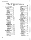
ADJUSTMENT
Introduction
....
5-1
Equipment
Required
..........
5-1
ADJUSTMENT
PROCEDURE
................
5-2
PREPARAT|ON
.............
.....5-2
1.
Adjust
Low
Voltage
power
Suppty
... 5-3
2.
Adjust
Z-Axis
and
High
Voltage
Circuits
.........
5-5
3. Adjust
Deflection
Amptifier
Gain
and
Frequency
Response
.............
5-6
4.
Adjust
Digital
Storage
Calibration
....
5-g
5.
Adjust
Sweep
Timing
....
5-g
6.
Adjust
Frequency
Gontrol
System
and
Dot
Marker
Position
....
S-g
7.
Adjust
Log
Amplifier
.........................
5-11
8. Adjust
Resolution
Bandwidth
and
Shape Factor
..............
5-14
9. Preset
the Variable
Resolution
Gain
and Band
Leveling
.....,..................
5-19
10. Adjust
Calibrator
Output Levet
........
5-20
11. Adjust
lF
Gain
..............
S-20
12. Adjust
B-SAVE
A
Refergnce
Level
.........
.......5-21
13.
Adjust
Preselector
Driver ................
S-21
14.
Adjust
Band
Leveling
for
Coaxial
Bands
...................
5-24
Section
6
Page
15. Adjust
Band
Leveling for
Waveguide
Bands
..............
5-25
16. PhasE
Lock
Calibration ....................
5-2S
OPTION INSTRUMENTS
ONLY .............
5-29
17.
Adjust
Option 07
VR Band Leveling
5-29
18. Adjust
Option 42 Module
.................
5-29
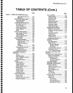
MAINTENANCE
TNTRODUCTTON
...............................
6-1
Removing
the
lnstrument
from its
Cabinet
..........
6-1
static-sensitive
components .......
6-1
PREVENTIVE
MAINTENANCE
...............
6.2
Elapsed Time
Meter
.....................
6-2
Cleaning
......-............
6-2
Lubrication
...............
6-2
Fixtures and
Tools
for Maintenance
.................,.........
6-2
Visual lnspection
..........................
6-2
Transistor and Integrated
Circuit Checks
..........
6-2
Performance
Checks
and Recalibration
.........................
6-3
Saving Stored Data
in
Battery-Backup
Memory
...............
6-3
TROUBLESHOONNG
........6.3
Troubleshooting
Aids ...................
6-9
Diagrams .............
6-3
Circuit
Board
lllustrations and
Component
Locator Charts .....
6-4
Diagnostics ..........
6-4
General
Troubleshooting
Techniques ...............
6-4
Semiconductor Checks
............
6-4
Diode
Checks
..........................
6-4
Diagnostic Firmware
................,...
6-5
Troubleshooting
Steps
.................
6-5
DTAGNOSTTCS
......................................
6-5
TROUBLESHOOTING
USING
THE
ERROR
MESSAGE DISPLAY
.... 6.5
Introduction
..............6-5
Combination of
Error
Messages
...
6-6
Procedure Format
.... 6-6
TRACE MODES
............
6-14
Alternate Frequency Display
........
6-14
Auxiliary Synthesizer Control .......
6-14
Correction
Disable/Enable ........-...
6-14
coRRECTtVE MATNTENANCE ..............
6-15
Handling Static
Sensitive
Components
.............6-1
5
Obtaining
Replacement Parts .......
6-1
5
Parts
Repair
and Return
Program ...................
6-1
5


