


Specification
-
494A1494Ap
Service,
Vol.
1
Characteristic
HORIZITBIG
(Rear
Panel)
Sweep Input
Voltage
Range
Trigger
Input
Voltage
Range
Minimum
Maximum
dc
+
peak
ac
Pulse
Width
MARKERIVIDEO
(Rear
Panet)
Video
lnput
Level
Marker
Input
Level
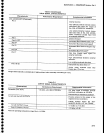
J104 ACCESSORY (Rear
Panet)
Pin
1
Pin
2
Pin 3
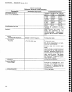
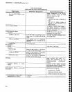
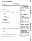
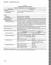
Table
2-3
(Continued)
INPUT
SIGNAL
CHARACTERISTICS
Supplemental Inf
ormatlon
Dc
coupled
input
for
external
hor-
izontal
drive
(selected
by
the EXT
position
of
the front-panel
TIME/DIV
control)
and
ac
coupled
input
for
external
trigger
signals (selected
at
other
positions
of
the
TIME/Dlv
con-
trol).
0 to +10V
(dc
*
peak
ac)
tor
tutl
screen
deflection
50v
30
vrms
to 10
kHz,
linearly
to 3.5 Vr." at
above.
0.1
rs
minimum
External
Video
input
or External
Video
Marker
inpul,
switched
by
pin
1
0f the
J104 ACCESSORY connec-
tor.
0to*4V
0 to
-10
V
lnterfaces with
Tektronix
1405
Side-
band
Adapter.
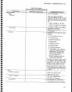
25-pin connector
(Not
R5-232
compatible)
Provides
bi-directional
access
to the
instrument
bus.
Also
provides
exter-
nal
Video select and external
preselector
drive.
Except for
the
external
preselector
drive
output, all
lines are TTL
compatible.
Maximum
voltage on all
lines is
+'l5 v.
External Video
Select
Low selects External
Video
lnput.
High
(default)
selects
Video
Marker
Input.
External
Preselector
Drive
Drive
signal
for an
external
preselec-
tor. Output
voltage
is
proportional
to
frequency change
(only
in
Bands
2-s\.
External Preselector Return
Ground
return for
the
External
Preselector
siqnal.
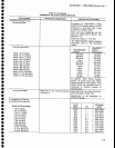
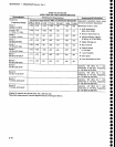
then
derate
1
00
kHz
and
t
o
o
I
a
a
t
o
a
I
I
I
o
I
o
o
,o
o
o
o
a
o
e
o
o
I
t
o
a
o
a
o
o
o
o
o
a
C
o
o
o
a
t
o
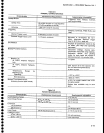
At least
1.0 V
peak
from
15 Hz
to
1 MHz
2-12