


DIGITAL
CONTROL (Diagram
9)
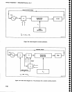
The Digital
Control
section provides
operator
and
digital
controller
interfaces.
lt
translates
changes
in
front-panel
controls
and,
for
the
programmable
version,
also
translates
instructions
received
via
the
GplB
into
codes
that control
the
instrument.
The
user interface
to
th€
digital
control
operating
program
is
discussed
in
the
Operators
and
program-
mers
manuals.
This
description
focuses
on
the rnajor
circuits
that
make
up
th€
Digital
Control
section.
Those
circuits
are:
.
Microcomputer
o
Addressable
registers
on
the instrument
bus
.
Front
panel
o
Accessories
Interface
o
GPIB Interface
Microcomputer
ThE
Microcomputer
system
receives
inputs
from
the
front-panel
controls,
the
instrument
circuits,
and
the
GPIB
(programmable
version
onty),
and
sends
control
codes
to
the
instrument
hardware
to set
it for
desired
operation.
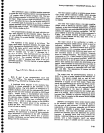
The
Microcomputer
consists
of
a
micropro_
cessor,
memory,
various
input/output
(l/O)
circuits,
and
associated
bus structures.
The
circuits
are
located
on
the Processor (A58),
Memory
(A54),
and
GptB
(A56)
assemblies.
The microcomputer
is
centered
around
a micropro-
cessor.
Input/output
(l/O)
is
provided
by
a
Timer,
a
Peripheral
Interface
Adapter
(plA),
and
for
the
program-
mable version
a Direct
Memory
Access (DMA)
ioniroller
and
a
General
Purpose
lnterface
Adapter
(GFIA).
Sys_
tem memory
includes
both read-only-memory
(ROM)
and
random-dcc€sS:rn€mory
(RAM).
The
ROM
contains
the instrument
operating
syst€m
and
other
firmware.
Front-pan€l
control
s€ttings,
displays,
and
calibration
information
are
stored
in
non-volatile
RAM.
This
RAM
has
battery
backup power
to retain
the
data
when
instrument
power
is
off.
The
instrument
operating
sys_
tem
uses additionat
RAM.
The
microprocessor
communicates
with
the
memory
and
l/O
ports
via
the
microcomputer
bus.
Communica-
tion with
the rest
of
the
instrument
is
via
the instrument
bus.
Interrupts
from
various
circuits
can
request
proces-
sor service.
The firmware
contains
a service
routine
for
each
of
the
interrupts.
lf
necessary,
the
processor
can
7-88
Theory
of
Operation
-
494[l4g4Ap
Service,
Vot.
1
mask,
or ignore, all
interrupts
except
for
a
power
failure
interrupt.
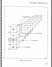
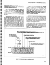
The
accompanying
illustrations show
the
address
allocations
for
the microcomputer.
These
will
be
useful
for
the following
descriptions.
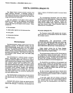
Figure
7€0
shows
the
entire address
range
of
the
processor.
Figure
7-31
shows
th€
l/O address
range.
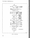
Figure
7€2
shows
plA
and
Timer memory
maps.
Unless othewyise
noted,
all
addresses
are
in hexadecimal.
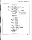
Processor
(Diagram
41)
The
Processor
board
(A58)
contains
the micropro-
cessor
and
most of
its
peripheral
devices
that compose
thE computer
system.
Microprocessor.
The
microprocessor,
Ul025,
processes
datai
generates
addresses
and control
sig-
nals,
and
controls
the
operation
of
the instrument.
The
microprocessor,
a
6808
(also
known
as
671271, has an
8-bit bi-directional
data
bus
and
a 16-bit address
bus.
Output signals
include
the
02
Clock
(Enable),
ReadfA/rite (R/W),
Bus Available (BA),
and
micropro-
cessor Valid
Memory
Address
(VMA).
The
microprocessor
divides
the CRT
Clock
signal
by
four,
producing
an
intemal
two-phase
clock.
This
clock
is
available at
the microprocessor's
Enable
output as
a
signal
f abeled
d2
Clock.
The
853.3
kHz
02
Clock drives
the Timer, PlA,
and DMA
Controller,
and it is one
of
the
control
lines available on
the microcomputer
bus.
The
Read/Write
line indicates
to the
peripheral
and
memory circuits
wheth€r
the microproc€ssor
is in
the
r€ad
state
(high)
or
the
write state
(low).
The read state
is
the
normal
standby condition
and a response
to a
halt signal.
U10308 and U2030F
buffer the
R/W
signal
to
drive the various circuits.
The
Bus Available
signal
goes
high
to
indicate
when
the
microprocessor
releases
th€ data bus. This occurs
when
the
microprocessor
executes a WAIT
or when
the
HALT lnput
goes
low.
A high
VMA
signal
tells
the
memory
circuits
that
the,re is a valid address on
the
microcomputer address
bus.
U3036C
issues
the
VMA signal
to the
memory
cir-
cuits from
either
the
microprocessor
or
the
DMA Con-
troller.