


Maintenance
-
494A/4g4Ap
Servlce
Vot.
1
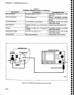
5. Setting
Sweep
Range
a.
Apply
5
ps
time
markers
from
the
Time
Mark
Generator
to the
RF tNpUT.
Set
the FREO
SPAN/D|V
to
500 kHz
then
back
to 200
kHz
to center
the 2nd LO
frequency.
b. Adjust
the
REF
LEVEL
to disptay
the
200
kHz
markers
then center
one
of
the markers
with
the
CENTER FREOUENCY
controt.
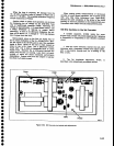
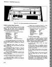
c.
Adjust
the 2nd
LO
Sweep
R1O6Z,
on
the
Span
Attenuator
board
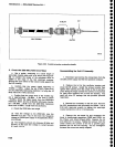
(Figure
6241,
so
the
comb
lines on
opposite
sides
of
the screen,
are
exactly
g
major
divi_
sions
apart.
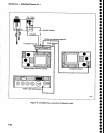
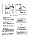
6. Check
and
Adjust
Tune
Linearity
a.
With
Frequency
Corrections
disabled
(see part
2), apply
5
ps
markers
from
a
Time
Mark
Generator
to
thE
RF INPUT.
SEt thE FREQUENCY
tO 20
MHZ.
FREQ
SPAN/DIV
to 200
kHz
and
activate
AUTO
RESOLN.
Adjust
th€ REF
LEVEL
so
a comb
of 200
kHz
markers
is
displayed.
b.
Turn
the
CENTER
FREQUENCY
controt
count€r-
clockwise
until
the
c€nter
frequency
stops
tuning,
decrease FREQ
SPAN/D|V
to
50
kHz
then
tune tfre
CENTER FREQUENCY
up
untit a
marker
signal
is one
major
division
from
the left
edge
of
the
graticule.
A
comb line
(or
marker
signal)
should
appear
on
or near
the
first
major
division
in from
the right
sid€
of th€
scr€en.
c.
lt
the
right
marker
is
not
exacily
g
divisions
from
the
left
marker,
note
the
€rror
to th€ nearest
0.5 minor
division.
d.
Tum
the
CENTER
FREQUENCY
control
ctock-
wise,
to increase
center
frequency,
until
the next
marker signal
is one
divislon
in
from
the lett
edge and
again note
thE
spacing
between
this
marker
and
the
marker
near
the right
edge.
e.
Continue
this
process
of
tuning
up
in
frequency
until the
center
frequency
stops
tuning, noting
the slgnil
spacing
at each
check
point.
f.
lf
the
peak-to-peak
enor
is 2.5
minor
divisions
(25
kHz) or
l€ss,
the lin€arity
over
the center
2
MHz
of
swEep is
satisfactory;
if
more,
the shaper
needs
adjust-
ment or
repair.
g.
Switch
the
FREQ
SPAN/D|V
to 200
kHz,
tune to
the
low end
of
the sweep
range
and note
the
linearity
over the center
eight
divisions
of
span,
then
tune to the
high
end
of
the 2nd
LO
range
and
again
note
the
linear-
ity. Peak-to-peak
deviation
should
not
exceed
0.5
minor division.
h.
lf
the
shaper
needs
adjustm€nt
or
repair proceed
as follows:
o
o
o
o
o
o
o
t
o
a
o
t
o
O
o
I
o
o
o
a
a
o
o
o
a
o
a
o
o
t
t
o
o
o
o
a
t
o
a
o
o
a
o
a
6-42
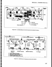
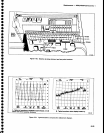
(1)
A shaper
diode or resistor
may
be
defective
if
the comb
line spacing
is consistent
for
part
of
the
tuning range
and
30 kHz or
tnore off for
the
other
parts
of
the
sweep.
To
test
the
diodes
for forward
conduction,
tune to
the
low
end of
the
range
and
short
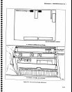
R2049
(Figure
6-20).
The
output
of
U1073A
(pin
1) should
equal
about
*3V.
Ut0S9
diodes
B
through
G and U2059
diodes
A through
F should
ail
have
a
0.48 V
forward drop.
Use
a
floating
or
digital
voltmeter
to
check the
drop.
(21
Tum
POWER
off
then temporarily
replace
Shaper
resistor
R2049 with a
20 kO
potentiometer.
Switch POWER on,
and
adjust the
potentiometer
to
obtain
the
best
overall
linearity;
decreasing
resls-
tance will
decrease the spacing between
comb
lines
in
the upper
portion
of
the tune range and
spread
the spacing
for the lower
portion.
Increasing
the
resistance
of
R2049 will reverse
the effect.
When
the correct
setting is found,
turn
POWER
off, meas-
ure
the
resistance,
and replace with
a fixed
resistor
of
the same or
near the same
value.
i.
Check the
tun€
sensitivity
and sweep
range
of
the
2nd LO. Repeat
steps 4,
5,
and
6 if
necessary.
7. Conclusion
a.
Replace
the
housing
lid with its 14 screws.
b. Tighten
the screws
sequentially,
starting
from
the
center of
the
lid and
progressing
toward the
corners
to
prevent
gaps
between the
lid
and
the housing.
Use
care
to
not
strip
the
screws as
you
tighten
them.
c.
This completes
the 2182 MHz
Phase
Locked 2nd
LO
calibration.
Refer to
"Adjust
control
system" in Sec-
tion
5
for
readjusting the system.
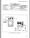
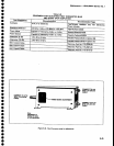
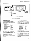
Troubleshooting
Aids for
the
2182
MHz Phase
Locked 2nd LO
Assembly
lf
the Phase Locked assembly
is in
the
instrurnent,
set the
FREQ
sPAN/Dlv to 500
kHz
or more so the 2nd
LO
is not sweot.
The
difference frequency signal
(18
MHz) from
the
2200 MHz
Reference Mixer is amplified and fed
to
P224.
Nominally,
its
amplitude
is
-5
dBm into 50O.
P224
is convenient
for monitoring the 16-20 MHz
VCO. When
phase
lock
is operating, the difference
fre-
quency
exactly
equals the
frequency
of
the
vco. lf
phase
lock
is
not
functioning
properly,
the difference
frequency signal
will
either
disappear
completely
or
tune
to
its range
limit
of
-6
MHz or 30 MHz.